|
|
Original instructions
|
|
Step
|
Action
|
|---|---|
|
1
|
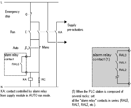
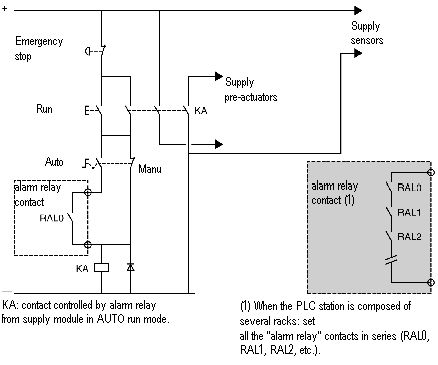
Switch on the power supply to the PLC and the inputs (sensors), using the contactor KM (see diagram).
|
|
2
|
When the PLC is in RUN mode and running on MANU/AUTO, switch on the output power supply (pre-actuators), using the contactor KA. Only in AUTO, this is controlled by the alarm relay contact in each power supply.
Note:
In alternating current, the contactor KA controls the supply sensors.
In direct current, the contactor KA controls the supply pre-actuators and the supply sensors.
|

