The Graphic Editor applet's top window consists of several "dialog panels," only one of which is visible at any time. Switching from one dialog to another is done by clicking buttons on the current dialog. This topic describes the dialog panels that compose the top window.
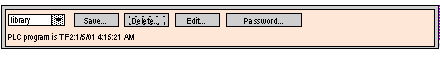
The Top Dialog is the dialog panel that is initially shown in the top window when the Graphic Editor applet is started. Access to other dialog panels of the top window is from this dialog.
The controls of the Top Dialog provide the following functions:
-
Drop-down List. The drop-down list box shows graphic display files that have been saved to the Web server module and are available for retrieval. When you select a graphic display from this list, the graphic display currently in the window is replaced with the selected one. If the current graphic display has been modified since it was last saved, you are asked for confirmation that the changes are to be discarded. If the special entry <new> is chosen from the list, the display window is cleared and a new graphic display can be created.
-
Save. The Save button makes the Save Dialog visible. This button is disabled until you have entered a correct write-enabled password.
-
Delete. The Delete... button makes the Delete Dialog visible. This button is disabled until you have entered a correct password, or if the current graphic display has not yet been saved.
-
Edit. The Edit... button makes the Edit Dialog visible.
-
Password. The Password... button makes the Password Dialog visible.
-
Information display area. The information display area shows the name and version of the Concept, PL7, or Control Expert program that is running in the connected PLC.
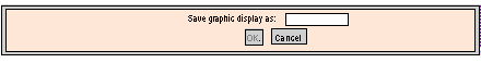
The Save Dialog allows you to save the current graphic display.
When the Save Dialog is presented, the name of the current graphic display is shown in the dialog’s text field. If the current graphic display has not been saved (i.e., a "new" graphic display), then the text field is blank. Once you have either accepted the current name (with a "save" operation) or provided a new name (with a "save as" operation), then you can click the OK button to save the contents of the current graphic display to the Web server module. The Cancel button will cause the Top Dialog to be shown again, with no action being taken.
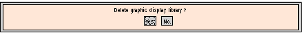
The Delete Dialog allows you to delete the current graphic display.
If you click Yes, the existing graphic display window is cleared and the graphics file on the Web server module is deleted. Clicking No will cause the Top Dialog to be shown again, with no action being taken.
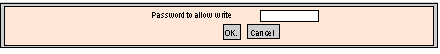
The Password Dialog allows you to enter the password that enables those user functions that modify graphic display files or PLC run-time data values.
If you enter the correct password and click OK, then you will be allowed to save and delete the current graphic display. Correct entry of the password also permits you to write new values to the PLC (via those graphic objects that support writing values to a PLC, if any). Clicking OK when the text field is empty clears the current password permissions (if there are any). The Cancel button redisplays the Top Dialog without changing the current password permissions.
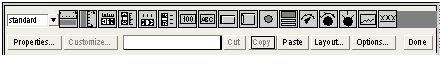
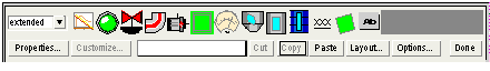
The Edit Dialog allows you to select a graphic object for placement in the display window, and provides access to graphic editing functions. The available graphic objects are presented in a set of palettes, with one palette visible at a time. There are two palettes.
The standard palette:
The extended palette:
The controls of the Edit Dialog provide the following functions:
-
The Drop-down List Box shows the set of available palettes. When you select the name of a palette from the list, the graphic objects in that palette appear in the palette display area of the dialog.
-
The Palette shows the graphic objects in the current palette. An icon depicts each graphic object's type (meter, button, etc.). When you click any icon in the palette, a graphic object of the corresponding type is selected for insertion. If you click in an open area of the display window while the Graphic Editor is in "insert mode," an instance of the selected graphic object is inserted into the graphic display.
-
The Information Area shows the name and size of the graphic object that is currently selected.
-
The Cut button causes the currently selected graphic object(s) to be removed from the graphic display and saved to a buffer (i.e., an internal clipboard), replacing the existing contents of the buffer.
-
The Copy button causes the currently selected graphic object(s) to be copied to the buffer, replacing the existing contents of the buffer.
-
The Paste button causes the content of the clipboard to be inserted into the upper left corner of the graphic display. The pasted graphic objects can then be moved to the desired location in the display.
-
The Properties button displays the currently selected graphic object’s Property Sheet.
-
The
Customize button displays the currently selected object’s
Customizer (if the graphic object has one).
-
The Layout button makes the Layout Dialog visible.
-
The Options button makes the Options Dialog visible.
-
The Done button makes the Top Dialog visible again.
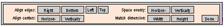
The Layout Dialog allows you to change the position and size of a group of graphic objects.
The controls of the Layout Dialog provide the following functions:
-
For aligning the edges of graphic objects, the Right, Bottom, Left, and Top buttons move the selected graphic objects so that their specified sides are at the same position. Select at least two graphic objects to enable these buttons.
-
For aligning the center lines of graphic objects, the Horizontally and Vertically buttons move the selected graphic objects so that their horizontal or vertical center lines, respectively, are at the same position. Select at least two graphic objects to enable these buttons.
-
For positioning graphic objects so that they are evenly spaced, the Horizontally and Vertically buttons move the selected graphic objects so that either the horizontal or vertical spacing between the objects is the same. Select at least three graphic objects to enable these buttons.
-
To automatically size graphic objects, use the Width and Height buttons to re-size the currently selected graphic objects so that either the widths or heights, respectively, of the objects match. Select at least two graphic objects to enable these buttons.
-
The Done button makes the Edit Dialog visible again.
NOTE: For most layout operations (except Space evenly) one of the selected objects is considered the "reference object" to which the other selected objects adjust for their new position or dimension. For example, when the "Width" button is pressed, the selected objects have their widths changed to match that of the reference object. The reference object is differentiated from the other selected objects by making its selection box a different color than the others.
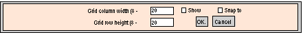
The Options Dialog allows you to change the settings related to a grid that can be drawn in the display window. The grid is solely for assistance in editing a graphic display and is shown only when the Graphic Editor is in "edit mode." Edit mode starts when you switch to the Edit Dialog and ends when you return to the Top Dialog.
The Options Dialog controls provide the following functions:
-
The cell size of the grid can be changed by the entering the grid's column width and row height in the dialog's text fields.
-
If the Show grid check-box is checked, the grid is drawn; otherwise, no grid is shown.
-
If the Snap to grid check-box is checked, then, when you change the size or position of a graphic object, the changed coordinate(s) or dimension(s) is automatically adjusted to coincide with a grid point.
-
The OK button causes the current option settings to become active, and the Edit Dialog to be shown again.
-
The Cancel button causes the Edit Dialog to be shown again, with no option settings being changed.