|
Communication Module Diagnostics in Control Expert
|
|
|
Original instructions
|
|
Step
|
Action
|
|---|---|
|
1
|
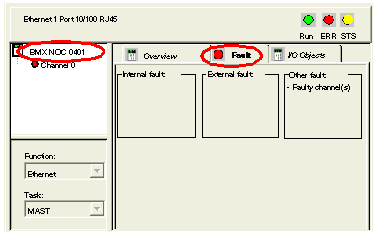
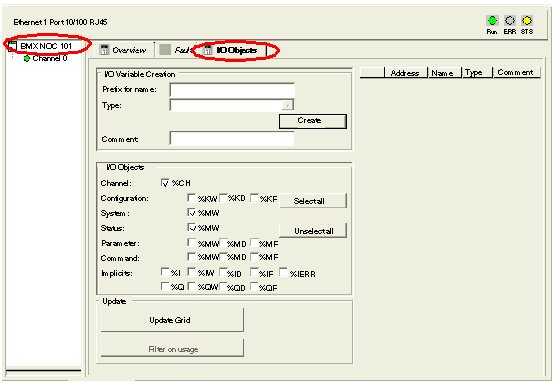
In the Channel area, select the communication module. The following pages are displayed:
|
|
2
|
To display the communication module’s active detected faults, click on the Fault page:
 |

|
Step
|
Action
|
|
|---|---|---|
|
1
|
Configure the READ_STS function block, as follows:
 Where:
|
|
|
r = rack or station number
|
||
|
m = module or slot number
|
||
|
MOD = a constant indicating module data
|
||
|
2
|
To view the data updated by the READ_STS function block, enter the corresponding direct addresses in the Control Expert Animation table, or use them in your program logic:
|
|
|
Object
|
Description
|
|
|
%Ir.m.MOD.ERR
|
Module detected error bit
%Ir.m.MOD.ERR is implicitly updated based on %Ir.m.0.ERR
|
|
|
%MWr.m.MOD.0
|
Exchange Status:
Bit 0: reading of module status in progress
|
|
|
%MWr.m.MOD.1
|
Exchange Report:
Bit 0: detected error while reading module status
|
|
|
%MWr.m.MOD.2
|
Bit 0: internal fault detected
|
|
|
Bit 1: operational fault detected
|
||
|
Bit 2: not used
|
||
|
Bit 3: self test
|
||
|
Bit 4: not used
|
||
|
Bit 5: configuration fault detected
|
||
|
Bit 6: missing module or off
|
||
|
Bit 7: not used
|
||
|
Step
|
Action
|
||
|---|---|---|---|
|
1
|
Configure the READ_STS function block, as follows:
 Where:
|
||
|
r = rack, or station, number
|
|||
|
m = module, or slot, number
|
|||
|
ch = channel number—set to 0 for ETC transactions
|
|||
|
2
|
To view the data updated by the READ_STS function block, enter the corresponding direct addresses in the Control Expert Animation table, or use them in your program logic:
|
||
|
Object
|
Description
|
Standard Symbol
|
|
|
%Ir.m.ch.ERR
|
Channel detected error bit
|
CH_ERROR
|
|
|
%Ir.m.ch.0
|
Status of Ethernet services:
|
—
|
|
|
Bit 0: EIP Scanner (0 = OK, 1 = NOK)
|
—
|
||
|
Bit 1: EIP Adapter (0 = OK, 1 = NOK)
|
—
|
||
|
Bit 2: EIP Client (0 = OK, 1 = NOK)
|
—
|
||
|
Bit 3: EIP Server (0 = OK, 1 = NOK)
|
—
|
||
|
Bit 4: Modbus scanner (0 = OK, 1 = NOK)
|
—
|
||
|
Bit 5: Modbus TCP Client (0 = OK, 1 = NOK)
|
—
|
||
|
Bit 6: Modbus TCP Server (0 = OK, 1 = NOK)
|
—
|
||
|
Bit 7: FDR Server (0 = OK, 1 = NOK)
|
—
|
||
|
Bit 8: RSTP (0 = OK, 1 = NOK)
|
—
|
||
|
Bit 9–Bit 15: reserved
|
—
|
||
|
%MWr.m.ch.0
|
Exchange Status:
|
EXCH_STS
|
|
|
Bit 0: reading of status words of the channel in progress
|
STS_IN_PROG
|
||
|
Bit 1: command write in progress
|
CMD_IN_PROG
|
||
|
%MWr.m.ch.1
|
Exchange Report:
|
EXCH_RPT
|
|
|
Bit 0: detected error while reading channel status
|
STS_ERR
|
||
|
Bit 1: detected error while writing a command to the channel
|
CMD_ERR
|
||
|
2
cont’d
|
%MWr.m.ch.2
|
Standard channel status (low byte):
|
—
|
|
Bits 0...3: reserved (0)
|
—
|
||
|
Bit 4: internal fault detected
|
—
|
||
|
Bit 5: not used (0)
|
—
|
||
|
Bit 6: X-Bus communication fault detected
|
—
|
||
|
Bit 7: application fault detected (conf fault detected)
|
—
|
||
|
High byte:
|
—
|
||
|
Bits 0...7: reserved (0)
|
—
|
||
|
%MWr.m.ch.3
|
Ethernet Port Global Status:
|
ETH_PORT_STATUS
|
|
|
Bit 0: detected configuration error
|
—
|
||
|
Bit 1: the Ethernet interface is disabled
|
—
|
||
|
Bit 2: duplicate IP address detected
|
—
|
||
|
Bit 3: configuration mismatch
|
—
|
||
|
Bit 4: reserved
|
—
|
||
|
Bit 5: the module is in the process of obtaining an IP address
|
—
|
||
|
Bits 6...15: reserved
|
—
|
||
|
%MWr.m.ch.4
|
IP address (IP_ADDR):
|
IP_ADDR
|
|
|
—
|
||
|
—
|
||
|
—
|
||
|
—
|
||
|
—
|
||