

External Features
Legend:
Item |
Description |
Function |
|---|---|---|
1 |
Observe the LED display to diagnose the module. |
|
2 |
MAC address |
This manufacturer-defined address is unique for each individual module. |
3 |
memory card slot |
Store data logging files (.csv) to the SD card. |
4 |
serial port |
This port is an isolated RS232/RS485 serial connector. Use a TCSXCN3M4F3S4 cable (serial link) to connect the module's serial (RS232) RJ45 port to a communication port on a modem. The supports all pins on the modem's nine-pin D-sub connector except for the ring indicator (RI) signal pin (sold separately). |
5 |
This connection to the Modicon M580 rack supports Ethernet and X Bus communications. |
|
6 |
Use this switch to set the cyber security level for the module. |
Dimensions
Serial Port
The BMENOR2200H module has a built-in serial port that supports either serial communications through a serial link.
| Characteristic | Description |
|---|---|
| supported protocols | RTU protocols:
|
| connection | RJ45 socket |
| physical link |
|
Serial port pins: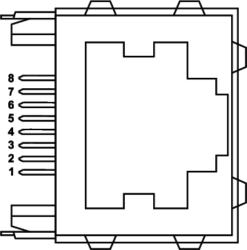
Pinout (functionality):
Pin |
Signal |
Pin |
Signal |
1 |
RXD |
5 |
D0/DSR |
2 |
TXD |
6 |
CTS |
3 |
RTS |
7 |
DCD |
4 |
D1/DTR |
8 |
common |
shielding |
|||
The RJ45 connector has eight pins. The pins used differ according to the physical link used.
The RS 232 serial link uses these pins:
pin 1: RXD signal
pin 2: TXD signal
pin 3: RTS signal
pin 4: DTR signal
pin 5: DSR signal
pin 6: CTS signal
The TCS MCN 3M4F3C2 serial crossover cable has two connectors:
RJ45 male
Nine-pin SUB-D female
These are the pin assignments between
an RJ45 plug and a 9–pin SUB-D socket for a TCSMCN3M4F3C2 serial crossover cable: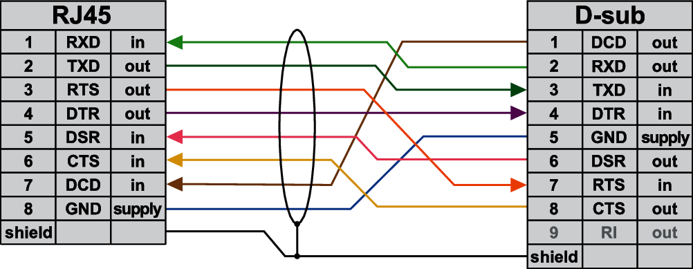
The RS 485 serial link uses these pins:
pin 4: D1 signal
pin 5: D0 signal
The serial link uses these pins as described here:
pin 7: not connected
pin 8: common of the network power supply (0 V)
Rotary Switch
A three-position rotary switch is located
on the back of the module. Set this switch to configure a cyber security
operating mode for the module: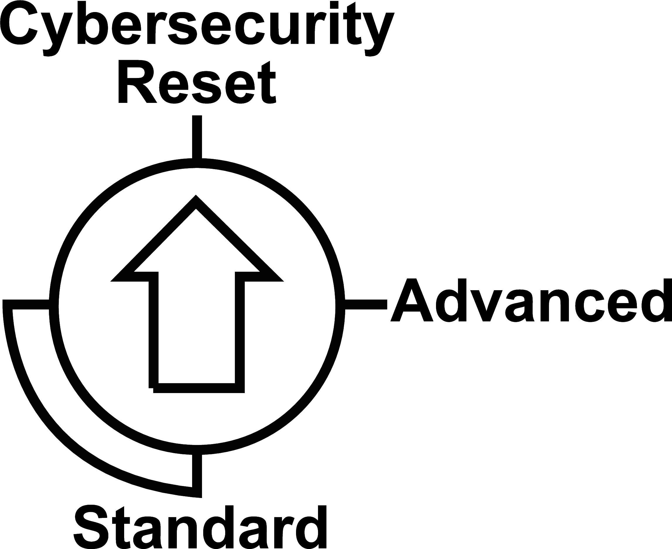
Refer to the detailed description of the cyber security rotary switch.
Accessories
These additional hardware accessories are available:
Description |
Comment |
|---|---|
dust cover |
Cover the module’s unused RJ45
ports with this stopper:
 The dust cover reduces the port’s exposure to atmospheric dust. |
screwdriver |
Use only the small, plastic screwdriver that was delivered with the module to set the rotary switch. |