

Introduction
The BMENOR2200H module has a dual-bus connector that supports both Ethernet and X Bus communications.
Use these instructions to install the module in a single slot on a BMEXBP Ethernet backplane.
Before You Begin
Take these steps before you insert the module on the rack:
Remove the protective cap from the module connector on the rack.
Determine the cyber security operating mode for the module and configure the appropriate cyber security mode with the rotary switch before you install the module in the slot. The selected mode is implemented only after a power-up of the module.
Backplane Considerations
Install the module only on the local rack. You can install and configure a maximum of four communication modules (including BMENOR2200H modules) on a single local rack (depending on the selected CPU).
This table shows the maximum number of BMENOR2200H modules you can install in the local rack with respect to specific CPU references:
CPU |
BMENOR2200H |
|---|---|
BMEP581020 |
2 |
BMEP582020 |
2 |
BMEP582040(S) |
3 |
BMEP584020 |
4 |
BMEP584040(S) |
4 |
BMEP586040 |
4 |
| BMEH582040 | 2 |
BMEH584040 |
4 |
BMEH586040(S) |
4 |
Install the module in a dual-bus slot on one of the following Ethernet backplanes:
Backplane |
Description |
|---|---|
BMEXBP0400(H) |
4-slot (hardened) Ethernet backplane |
BMEXBP0800(H) |
8-slot (hardened) Ethernet backplane |
BMEXBP1200(H) |
12-slot (hardened) Ethernet backplane |
BMEXBP0602(H) |
6-slot (hardened) dual-PWS Ethernet backplane |
BMEXBP1002(H) |
10-slot (hardened) dual-PWS Ethernet backplane |
Rack and Slot Restrictions
The module occupies a single dual-bus slot. Observe these restrictions:
Rack |
Slot |
Instruction |
|---|---|---|
all racks |
0, 1 |
These slots do not support the BMENOR2200H module.
NOTE: These slots are reserved
for the CPU module.
|
BMEXBP1200(H) |
2, 8, 10, 11 |
These X Bus-only slots do not support the Ethernet functionality of the dual-bus BMENOR2200H module. |
BMEXBP1002(H) |
2, 8 |
|
extended racks |
— |
You cannot install the dual-bus BMENOR2200H module in an extended rack. NOTE: Extended racks do not have Ethernet ports.
|
RIO drops |
— |
You cannot install the dual-bus BMENOR2200H module in an RIO drop. |
Cyber Security Switch Considerations
| NOTICE | |
|---|---|
Follow these steps every time you insert a BMENOR2200H module on a powered rack:
Step |
Action |
|---|---|
1 |
Set the rotary switch on the module to the Cybersecurity Reset position. |
2 |
Insert the module in the rack to power it up. |
3 |
Remove the module from the rack to power it down. |
4 |
Set the rotary switch on the module to the Advanced or Standard position. |
5 |
Reinsert the module in the rack to power it up. |
Installing the Module on the Rack
Mount the module in a single slot on the backplane:
Step |
Action |
||||
|---|---|---|---|---|---|
1 |
Turn off the power supply to the rack. |
||||
2 |
Remove the protective cover from the module interface on the rack. |
||||
3 |
Configure the cyber security level for the module with the rotary switch according to the cyber security considerations. |
||||
4 |
Notice sub-steps a. and b. in the graphic: 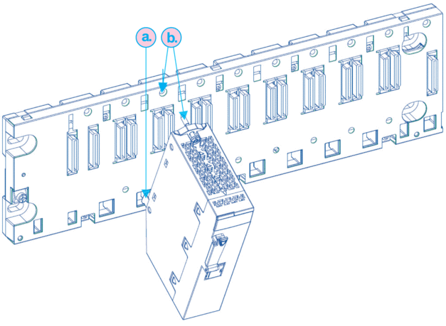
NOTE: Do not insert the BMENOR2200H module in slot 0 or 1 in the local rack. Those slots are reserved
for the CPU.
|
||||
5 |
Tighten the retaining screw to hold the module in place on the rack: 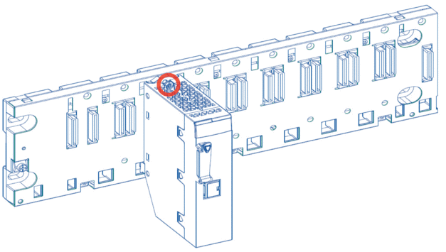 NOTE: Tightening torque: 0.4...1.5 N•m (0.30...1.10
lbf-ft).
|
||||
6 |
Insert the SD card if you intend to use the data logging feature. |
Replacing a Module
| NOTICE | |
|---|---|
Any module on the rack can be hot-swapped at any time with another module with compatible firmware. The replacement module obtains its operating parameters over the backplane connection from the CPU. The transfer occurs immediately at the next cycle to the device.
When you switch from Advanced to Standard operations or vice-versa, reset the module by setting the rotary switch to the Cybersecurity Reset position to implement a clean configuration file and clear the security settings (including the user name and password).
We suggest that you export your cyber security configuration before you replace the module. When the rotary switch is set to the factory Cybersecurity Reset mode, the entire cyber secure configuration is erased.
Replace the module:
Step |
Action |
|---|---|
1 |
Remove the module from the rack by reversing the above steps for installing the module. NOTE: Because this is a hot-swappable module, it is not necessary
to power down the rack to remove the module.
|
2 |
Set the rotary switch on the replacement module to the Cybersecurity Reset position. |
3 |
Insert the replacement module in the rack to power it up. |
4 |
Remove the replacement module from the rack to power it down. |
5 |
Set the rotary switch on the replacement module to the Advanced or Standard position. |
6 |
Reinsert the replacement module in the rack to power it up. |