Introduction to Transparency
You can segregate a network into multiple subnetworks to limit user access and increase performance. This usually means that devices in different subnetworks are not able to communicate directly.
You can, however, use the
IP forwarding functionality of the BMENOC0321 control network module to enable Ethernet network transparency to facilitate seamless communications between devices in different subnetworks. In M580 systems, use a BMENOC0321 module to achieve transparency between different types of devices in the control network, the device network, and the extended device network.
For example, you can run the Control Expert DTM software on a PC that is located in the to access configuration data, diagnostic data, and I/O data from devices in the (M580 CPU, ATV, TeSys, STB, etc.).
NOTE: The recommended maximum throughput for a BMENOC0321 module that uses the IP forwarding service is 1,350 packets per second.
Before you start this example, change your Control Expert configuration to facilitate the use of the IP forwarding service:
NOTE: If you download the application via a BMENOC0301/11 module, the module resets at the end of the download, which resets the connection between Control Expert and the module. If you download the application via the USB port on the M580 CPU, the connection is sustained.
Suppose you want to provide transparency between the control network and the device network:
-
On the control network, host A (a PC) use the IP address 172.168.100.1 in subnetwork 172.168.0.0.
-
On the device network, host B (an Advantys STB module) uses the IP address 192.168.10.200 in subnetwork 192.168.0.0.
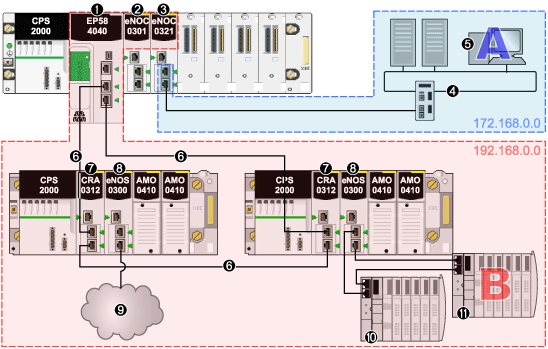
To facilitate communications between hosts A and B, connect the control network and device network physically, as well as logically. The IP forwarding service in the BMENOC0321 module is the interface for this network connection.
In the sample architecture, the IP forwarding service in the BMENOC0321 module provides transparency between the device network and the control network. Host A in subnetwork 172.168.00 (blue) can communicate with host B in subnet 192.168.0.0 (red) because the BMENOC0321 module has an address in both subnetworks:
1
A BME•58•••• CPU connects the local rack to the main ring.
2
A BMENOC0301 Ethernet communication module is connected to the CPU over the Ethernet backplane (so it is on the same network as the CPU).
3
The IP forwarding service on the BMENOC0321 module has IP addresses in three subnetworks (172.168.0.0 and 192.168.0.0).
4
A control network is in subnetwork 172.168.0.0.
5
A PC (host A) is in the control network.
6
The RIO main ring is connected to the CPU.
7
A BM•CRA312•0 (e)X80 EIO adapter module is on an RIO drop on the main ring.
8
BMENOS0300 network option switch modules are on RIO drops.
9
A DIO cloud connects to the main ring through the BMENOS0300 network option switch module.
10
An STB island in a DIO sub-ring connects to the main ring through the BMENOS0300 module.
11
Another STB island in the same DIO sub-ring includes the STB module that is host B in the device network.
In this example, the IP forwarding service of the BMENOC0321 module has three interfaces with different IP addresses in three subnetworks:
|
Network
|
IP Forwarding Service
|
|
IP Address
|
Sub-Network Mask
|
Network Address
|
Ethernet Interface
|
|
control network
|
172.168.30.1
|
255.255.0.0
|
172.168.0.0
|
ETH 2, ETH 3
|
|
device network
|
192.168.13.1
|
255.255.0.0
|
192.168.0.0
|
Ethernet backplane port
|
|
extended device network
|
10.20.1.1
|
255.255.0.0
|
10.20.0.0
|
ETH 1
|
Now that you have established the IP forwarding service, add the IP address forwarding information to the PC (host A) and the STB module (host B), which allows the hosts to send packets beyond their own subnetworks by utilizing the IP forwarding service of the BMENOC0321 module.
Configure the STB module to forward all traffic that is destined for outside its subnetwork to the BMENOC0321 module. That is, confirm that all traffic for networks other than 192.168.0.0 is forwarded to the appropriate interface of the BMENOC0321 module.
In this example, the appropriate interface of the BMENOC0321 module is its device network interface, which is at IP address of 192.168.13.1 in the same network as the STB module. This configuration is accomplished by setting the default gateway address of the STB module to be 192.168.13.1.
Configure the PC in a similar way. However, in a PC environment, it is possible to configure distinct rules about communications. To facilitate communications between the example PC in the control network and the devices in the device network, set the IP address of the BMENOC0321 module in the control network as the route for traffic that is destined for the device network.
The PC (host A) resides in the control network and is able to communicate with the BMENOC0321 module in the local rack via the module's control network IP address. For the PC to communicate with devices in the device network, add a static route to the PC, as in this example: c:\route ADD 192.168.0.0 mask 255.255.0.0 172.16.30.1
Where:
Use the optional "-p"” option to create a persistent route across system boots.
With this configuration, the PC sends all traffic destined for the device network (192.168.0.0) to the BMENOC0321 module (at IP address 172.16.30.1). The BMENOC0321 module then forwards the traffic to the appropriate device (and vice versa).
