|
|
Original instructions
|
|
Step
|
Action
|
|---|---|
|
1
|
Configure these modules on the local rack:
NOTE: The number of BMENOC0301/BMENOC0311 Ethernet communication modules depends upon your specific network design. You have the option to use these modules to extend the DIO scanning capabilities beyond the capacity of the selected M580 CPU. |
|
2
|
Confirm that the Ethernet backplane ports are enabled.
|
|
3
|
Install an Ethernet switch on the control network a distance equal to or less than 100 m from the BMENOC0321 module on the local rack.
NOTE: The switch does not have to be a managed dual-ring switch (DRS). |
|
4
|
Connect the control network port of the BMENOC0321 module (ETH 2 or ETH 3) to an Ethernet port on the switch on the control network.
NOTE: Refer to the Schneider Electric recommendations for cable types. |

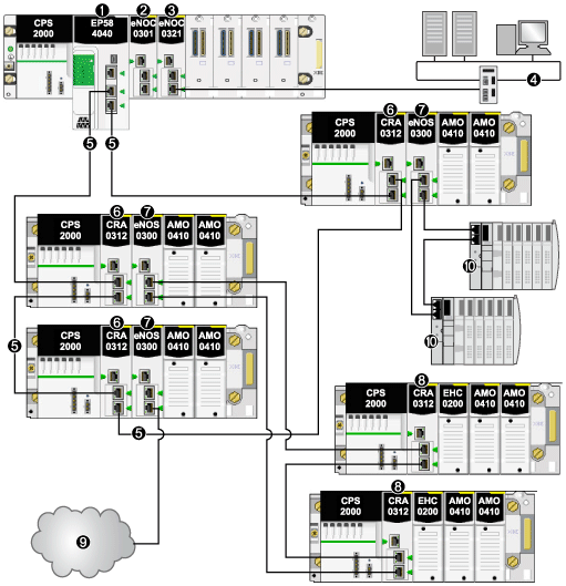
1BME•58•••• CPU connecting the local rack to the main ring
2BMENOC0301/BMENOC0311 Ethernet communication module on the local rack managing a number of distributed equipment nodes on the device network beyond the DIO scanning capacity of the M580 CPU
3BMENOC0321 control network module
4control network
5RIO main ring
6BM•CRA312•0 (e)X80 EIO adapter module on an RIO drop on the main ring
7BMENOS0300 network option switch module on an RIO drop
8BM•CRA312•0 module on an RIO drop on an RIO sub-ring
9DIO cloud connected to the main ring via a BMENOS0300 network option switch module on an RIO drop
10STB island in a DIO sub-ring connected to the main ring via a BMENOS0300 module on an RIO drop
|
Step
|
Action
|
|---|---|
|
1
|
Configure these modules on the local rack:
NOTE: The number of BMENOC0301/BMENOC0311 Ethernet communication modules depends upon your specific network design. You have the option to use these modules to extend the DIO scanning capabilities beyond the capacity of the selected M580 CPU. |
|
2
|
Confirm that the Ethernet backplane ports are enabled.
|
|
3
|
Install and connect two managed Ethernet switches via copper shielded twisted 4-pair CAT5e (10/100 Mbps) cable on the control network a distance equal to or less than 100 m from each other and from the BMENOC0321 module on the local rack.
|
|
4
|
Use copper shielded twisted 4-pair CAT5e (10/100 Mbps) cables to make these connections:
|

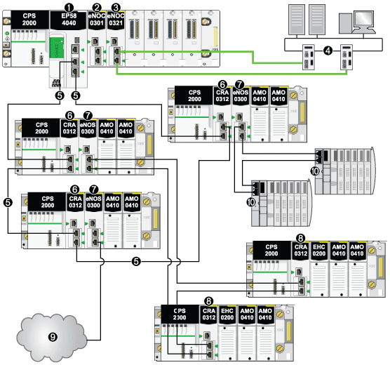
1BME•58•••• CPU connecting the local rack to the main ring
2BMENOC0301/BMENOC0311 Ethernet communication module on the local rack managing distributed equipment on the device network
3BMENOC0321 control network module (connected to control network via RSTP protocol in Gb dual ports)
4control network
5RIO main ring
6BM•CRA312•0 (e)X80 EIO adapter module on an RIO drop on the main ring
7BMENOS0300 network option switch module on an RIO drop on the main ring
8BM•CRA312•0 module on an RIO drop on an RIO sub-ring
9DIO cloud connected to the main ring via a BMENOS0300 network option switch module on an RIO drop
10STB island in a DIO sub-ring connected to the main ring via a BMENOS0300 module on an RIO drop