|
|
(Original Document)
|

|
Name
|
Default Value
|
Options
|
Meaning
|
|---|---|---|---|
|
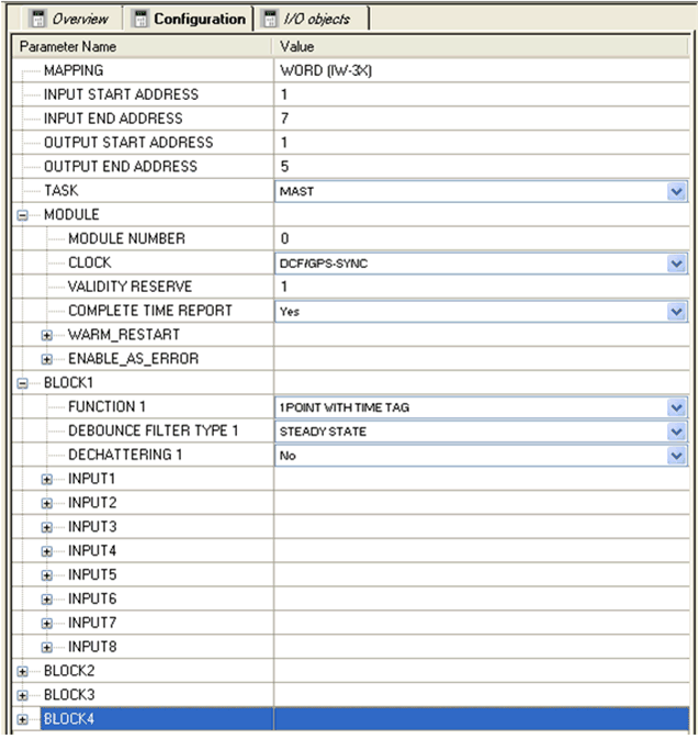
MAPPING
|
WORD (IW-3X)
|
-
|
The default value cannot be changed because the 140 ERT 854 10 module normally reads the raw values from the input words (%IW-3X) and writes them to the output words (%MW-4X).
|
|
INPUT START ADDRESS
|
1
|
-
|
Input starting address
|
|
INPUT END ADDRESS
|
7
|
-
|
The ending address for the inputs results from the starting address for the inputs plus 6 because the module occupies seven %IW registers.
|
|
OUTPUT START ADDRESS
|
1
|
-
|
Output starting address
|
|
OUTPUT END ADDRESS
|
5
|
-
|
The ending address for the outputs results from the starting address for the inputs plus 4 because the module occupies five %MW registers.
|
|
TASK
|
MAST
|
MAST/FAST(AUX0/AUX1/AUX2/AUX3 only with CPU 6•• ••, MAST only with a M580 CPU)
|
MAST = Master Task is assigned
FAST = Fast Task is assigned
AUX = AUX Task is assigned
The settings for MAST/ TASK/ AUX are defined during CPU configuration.
|
|
MODULE:
|
|||
|
MODULE NUMBER
|
0
|
1...127
|
User defined, inserted in event message. The uniqueness of the value is not checked. 0 = Default, no selection made
|
|
CLOCK
|
DCF/GPS-SYNC
|
DCF/GPS Clock
|
External synchronization in DCF77 format by the DCF or GPS clock.
|
|
Internal clock
|
Telegram synchronization. The clock runs either without monitoring or is monitored within a validity reserve.
|
||
|
No
|
Internal clock is deactivated
|
||
|
VALIDITY RESERVE
|
1 hour
|
1...254 hours
|
Internal clock: Time from the last synchronization until setting the TU bits and the time until the time stamp becomes invalid.
|
|
0
|
Internal clock: 0 = free run mode without elapsed time (TE/TU bits are not set)
|
||
|
1...5 hours
|
DCF/GPS Clock: 1 hour recommended
|
||
|
COMPLETE TIME REPORT
|
Yes
|
No/Yes
|
Switches the transfer of the complete time telegram (with month and year) on or off. Transfer of the complete time report is made as dummy event 1x directly before a time stamp event: the prerequisite is always transferring a time stamp event for monthly transitions, every start/stop of user programs, clearing the time stamp buffer, starting/setting the clock, otherwise the complete time report telegram is not sent.
|
|
WARM_RESTART:
|
|||
|
CLEAR COUNTERS
|
No
|
No/Yes
|
Clear counter on warm restart
|
|
CLEAR TIME TAG BUFFER
|
No
|
No/Yes
|
Clear FIFO buffer on warm restart
|
|
ENABLE_AS_ERROR:
|
|||
|
DCF GPS FAULT
|
No
|
No/Yes
|
Error values shown by the error LED "F". The enabled bits are treated as errors. Every disabled bit is treated as a warning (the error bits for an error during a self test are always set).
|
|
TIME INVALID
|
Yes
|
No/Yes
|
|
|
TIME NOT SYNCHRONIZED
|
No
|
No/Yes
|
|
|
BUFFER OVERRUN
|
Yes
|
No/Yes
|
|

|
Name
|
Default value
|
Options
|
Meaning
|
|---|---|---|---|
|
BLOCK
|
1...4
|
1...4
|
Number of the selected function block.
|
|
FUNCTION
|
1 POINT WITH TIME TAG
|
DISCRETE
|
Only binary inputs
|
|
COUNTER
|
Binary and counter values
|
||
|
1 POINT WITH TIME TAG
|
Binary + 1 bit event logging
|
||
|
2 POINT WITH TIME TAG
|
Binary + 2 bit event logging
|
||
|
8 POINT WITH TIME TAG
|
Binary + 8 bit event logging
|
||
|
DEBOUNCE FILTER TYPE
|
STEADY STATE
|
STEADY STATE/INTEGRATING
|
Debounce filter mode
|
|
DECHATTERING
|
No
|
No/Yes
|
Disabling/enabling the chatter filter
|
|
Name
|
Default value
|
Options
|
Meaning
|
|---|---|---|---|
|
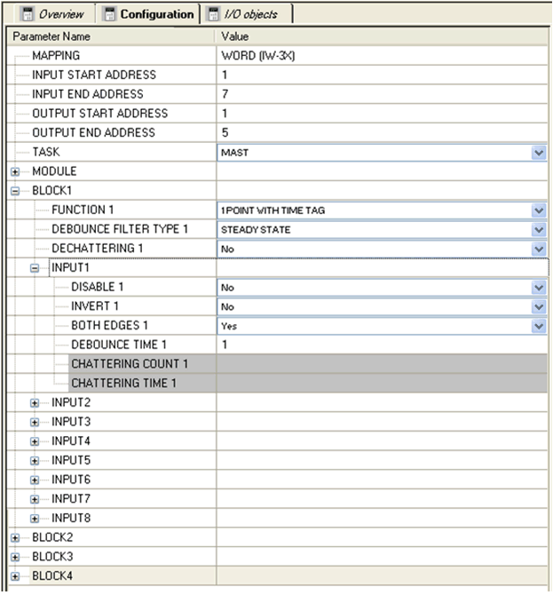
INPUT
|
1...32
|
1...8, 9...16, 17...24, 25...32
|
Input number sequence for the function block selected
|
|
DISABLE
|
No
|
No/Yes
|
Impedes processing of input data for the input (always 0)
|
|
INVERT
|
No
|
No/Yes
|
Reverse polarity of the input
|
|
BOTH EDGES
|
Yes
|
No/Yes
|
Edge monitoring for both edges
|
|
DEBOUNCE TIME
|
1
|
0...255
|
Debounce time 0... 255 milliseconds
0 = without internal SW delay
|
|
CHATTERING COUNT
|
0
|
0...255
|
Chatter number 0... 255 (for event/counter inputs)
0 = Chatter filter deactivated
|
|
CHATTERING TIME
|
1
|
1...255
|
Chatter filter time duration 1... 255*0.1 seconds
Note: This setting refers to two inputs next to each other!
|