Module Cabling
(Original Document)
Overview
This section describes the connection of time receivers, reference voltages and external input signals.
Reference Voltage
The input voltage range for the inputs is defined with the reference voltage. Reference voltages and input signals of the same group are to be protected with a common fuse. In addition, the inputs can also be individually protected.
NOTICE
MODULE DAMAGE
Never use the ERT module without a proper reference voltage to avoid damage to the module.
Failure to follow these instructions can result in equipment damage.
DCF 77E
Connection example for the ERT 854 10 with a DCF 77E time receiver
* 
UB(1), UB(2):24 ... 125 VDC, UB(3): 24 VDC, separate protection recommended
** 
not connected, suitable for support clamp for UB(3)
NOTE: The tightening torque must be between 0.5 Nm and 0.8 Nm.
NOTICE
DESTRUCTION OF ADAPTER
  • Before tightening the locknut to the torque 0.50...0.80 Nm, be sure to properly position the right-angle F adapter connector.
  • During tightening, be sure to maintain the connector securely.
  • Do not tighten the right-angle F adapter beyond the specified torque.
Failure to follow these instructions can result in equipment damage.
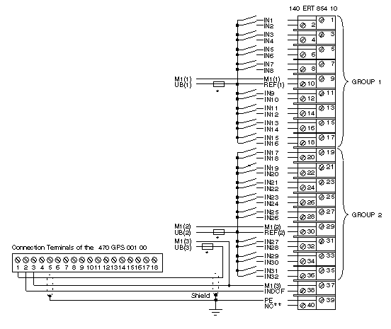
GPS 001
Connection example for the ERT 854 10 with a GPS 001 time receiver
* 
UB(1), UB(2):24 ... 125 VDC, UB(3): 24 VDC, separate protection recommended
** 
not connected, suitable for support clamp for UB(3)