IEC Data Object Mapping Page and Table
Original instructions
Data Object Mapping Page
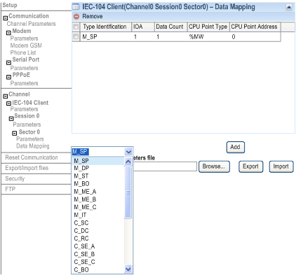
This figure shows the dialog box for configuring the data object mapping for an item with the example data type M_SP for IEC 60870-5-101/104 slave/server:
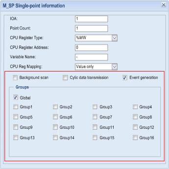
This figure shows the dialog box for configuring the M_SP data object mapping for IEC 101/104 server/slave:
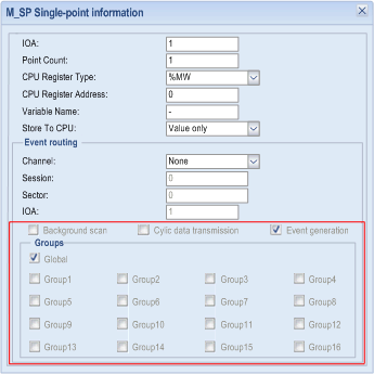
This figure shows the dialog box for configuring the M_SP data object mapping for IEC 101/104 client/master:
Mapping Table
Depending on the data object type and the selected protocol profile, different configuration fields are required to define a data object mapping item. This table describes the parameters:
Title
Value scope
Default value
Description
IOA
1...16777215
1
indicates the Information Object Address of the object.
Point Count
1...5000
1
indicates the number of objects defined. The IOA of each object is in sequence from the first object address.
CPU Register Type
%M/%MW/Unlocated
%MW
indicates the register type in CPU to map points.
CPU Register Address
0...30000
0
indicates start address of the register in CPU.
field only taken into account for located variables.
Variable Name
indicates the variable name of located or unlocated register
Store To CPU
Value only
Value with time
Value with quality
Value with quality and time
Value only
indicates the choice if the store time follows the value in the CPU registers.
CPU Reg Mapping
Value only
Value with time
Value with flag
Value with flag and time
Value only
choice the event time stamp source.
module: use the module time as time stamp of event.
CPU regs: use the time stamp in CPU registers.
Event routing
Channel
None/0/1
None
indicates the channel number to route.
Session
0
0
indicates the session number to route.
Sector
0/1/2/3/4
0
indicates the sector number to route.
IOA
1...16777215
1
indicates the Information Object Address to route.
Background scan
check box
unchecked
indicates that the background scan is enabled.
Cyclic data transmission
check box
unchecked
indicates that the cyclic data transmission is enabled.
Event generation (1)
check box
checked
indicates that events for points can be configured.
Groups
Global/1/2/3/4/5/6/7/8/9/10/11/12/13/14/15/16/C/B
check box
Global
defines data objects group responding for interrogation command from master/client. It can be combination of options.
1: 
This feature is available with firmware V1.7 or later.
%S and %SW
The configuration supports %S only for single point input, M_SP, and %SW only for analog input, M_ME_NA, for IEC slave.
NOTE: For %S and %SW, the CPU mapping does not support array due to the limits of the Control Expert.
Quality Bit/Flag Mapping
The website configuration supports quality bit/flag mapping to CPU register for monitor data-points for IEC master/slave.
NOTE: Use this feature in For M_SP, M_DP, M_ST,M_ME, M_ME_B, M_ME_C, and M_BO, M_IT.
The configuration reuses Timestamp Source in slave and Store To CPU in master, and expands two choices based on RTU V1.0. Master and slave have similar configuration pages for quality bits and flags.
NOTE:
  • For master, keep the parameter name Store To CPU.
  • For slave, change the name from Timestamp Source into CPU Reg. Mapping.
Behavior
Quality bit definition:
Point
Flag definition
Options
Comments
M_SP(SIQ)
single point information
bit 0:0/off/1/on
not used
reserved
bit 1:0
not used
bit 2:0
bit 3:0
blocked
bit 4:0 (not blocked) /1 (blocked)
substituted
bit 5:0 (not substituted) /1 (substituted)
not topical
bit 6:0 (topical) /1 (not topical)
invalid
bit 7:0 (valid)/ 1 (invalid)
M_DP(DIQ)
double point information
bit 0:1 (off)
not used
bit 1:1 (on)
reserved
bit 2:0
not used
bit 3:0
blocked
bit 4:0 (not blocked)/ 1 (blocked)
substituted
bit 5:0 (not substituted)/ 1 (substituted)
not topical
bit 6:0 (topical)/ 1 (not topical)
invalid
bit 7:0 (valid)/ 1 (invalid)
M_ST
M_BO
M_ME_A
M_ME_B
M_ME_C(QDS)
overflow
bit 0:0 (no overflow) /1 (overflow)
reserved
bit 1:1 (on)
not used
bit 2:0
bit 3:0
blocked
bit 4:0 (not blocked) /1 (blocked)
substituted
bit 5:0 (not substituted) /1 (substituted)
not topical
bit 6:0 (topical) /1 (not topical)
invalid
bit 7:0 (valid) /1 (invalid)
M_IT(sequence notation)
sequence number
bit 0...4:0...31
If the counter is frozen once, the sequence number increments 1.
carry
bit 5/ 0 (no overflow) /1 (overflow)
not supported in slave
counter adjusted
bit 6:0 (not adjusted) /1 (adjusted)
invalid
bit 7:0 (valid) /1 (invalid)
Input Float Value as Scientific
The input float values, as Scientific, are supported.
Long and Short Pulses
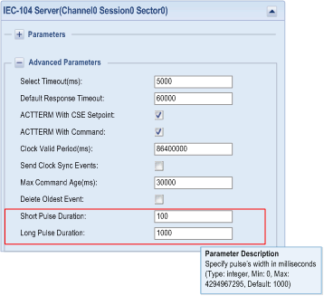
The protocol specification defines a qualifier value that is set by the master to determine the duration of the sort or long pulse. This parameter defines the number of milliseconds to be associated with a short or long pulse command. The configuration supports C_SC, C_DC, and C_RC for IEC server/slave.
This figure shows the pulse duration configuration:
When client/master sends pulse command to server/slave, the pulse duration is defined by controlled station. So the short/Long pulse duration needs to be configured on the website, and they are effective for C_SC,C_DC, and C_RC.
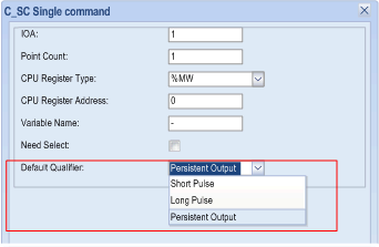
When configuring C_SC, C_DC and C_RC in server/slave, their default qualifier needs to be set. If you do not specify the client/master (qualifier is 0), the slave uses the pre-defined qualifier above.
This figure shows the qualifier configuration, the default qualifier is persistent output:
NOTE: C_SC,C_DC, and C_RC are triggered to update their value into CPU register only when server/slave receive command request from master, but not synchronized cyclically. Keep the corresponding CPU register not written by PLC application for end user.
Set Measured Value
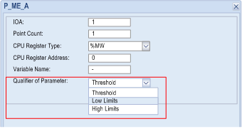
Support P_ME_NA_1, P_ME_NB_1, P_ME_NC_1 to set the low limits, high limits and threshold of the measured, scaled and float value. The parameters of the measured points are activated immediately after IEC 101/104 slave receives the request from IEC 101/104 master.
P_ME_A, P_ME_B, and P_ME_C in IEC 101/104 are used to set the parameter of the measured point for M_ME_A, M_ME_B, and M_ME_C. In IEC 101/104 master, they are command to set parameter of the measured point, but in IEC 101/104 slave they are used to store current parameter value. It is necessary to specify the qualifier when configuration both in IEC 101/104 master and IEC 101/104 slave.
This figure shows the parameter point setting of IEC 101/104 master:
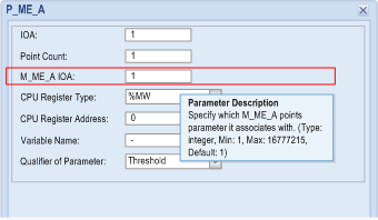
In IEC 101/104 slave, its configuration is same as IEC 101/104 master except IOA corresponds to the measure point such as M_ME_A IOA which is used to bind P_ME_A and M_ME_A.
This figure shows the parameter point setting of IEC 101/104 slave:
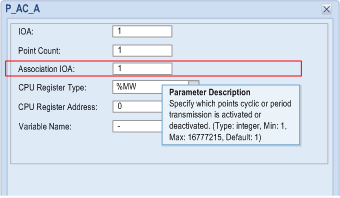
P_AC_A also need to bind a special IOA. It is different from P_ME_A, P_ME_B, P_ME_C, which may be set as any IOA for all monitor point types. P_AC_A is only used to activate/deactivate cyclic or period data transmission which is pre-defined in outstation. If outstation has no set neither of them, cyclic data transmission is activated or deactivated by default.
This figure shows the parameter point setting of IEC 101/104 slave:
Time Tag Parameter
Support control command with time tag (C_SC_TA, C_DC_TA, C_RC_TA, C_SE_TA, C_SE_TB, C_SE_TC, C_BO_TA) on IEC 104 server/IEC 104 client
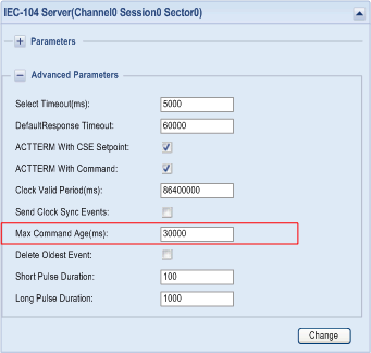
This figure shows the max command age setting IEC 104 server:
If a time tagged command is older than this period then the control operation is not taken. The default value for this field is 30,000 milliseconds. Values: 0...600,000 ms.
When Max Command Age(ms) is set to 0, the time tag is not checked.
The parameter Max Command Age(ms) only takes effect on time tagged command. The commands without time tag are accepted by IEC 104 server no matter how this parameter is configured.
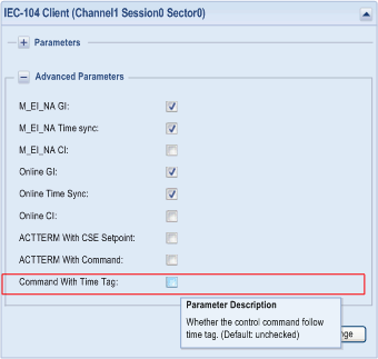
This figure shows the command with Time Tag IEC 104 client:
When command with time tag is enabled, the IEC 104 master only supports to send control command with time tag, otherwise, sends control command without time tag.