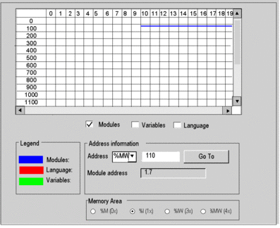
State RAM Memory Viewer
The following screen displays the content of the state RAM memory areas of the Momentum processor:

Description of the screen zones
Zone |
Description |
|---|---|
Table |
This table represents the mapping of the memory area selected with the selection buttons. The occupied memory addresses are marked by dashes:
The scroll bars can be used to access the entire memory area. |
, , and check-boxes |
These check-boxes are used to filter the information displayed in the table. If for example, is the only checkbox that is selected, only module-type information is displayed. |
|
By entering the object and its address in the fields and clicking the button, you display directly the address in the table (without using the scroll bars). This zone also has a display function; it displays the object and address of the box selected in the table. For module-type objects, it also gives the topological address of the module concerned. |
selection buttons |
These buttons are used to select the memory area to display in the table:
|


