

Overview
The 171 CBU 78090, 171 CBU 98090 and 171 CBU 98091 processors reside on top of a Momentum I/O base. Both processors are designed to fit on any Momentum I/O base.
You can snap a processor directly onto a Momentum I/O base, making connections at the following points:
2 plastic locking tab extensions on the processor fit into the slots on the left and right sides of the I/O base.
a 12-pin female power and communication connector on the processor fits into the 12-pin male connector on the base.
4 snap connectors on the top of the processor and 2 snap connectors on the bottom of the processor fit into receptacles on the base.
For an /O base with a fixed standoff ground-nut on its printed circuit board, a ground screw and a male-female standoff connect the processor to the I/O base.
The connection points on the back side of the processor:
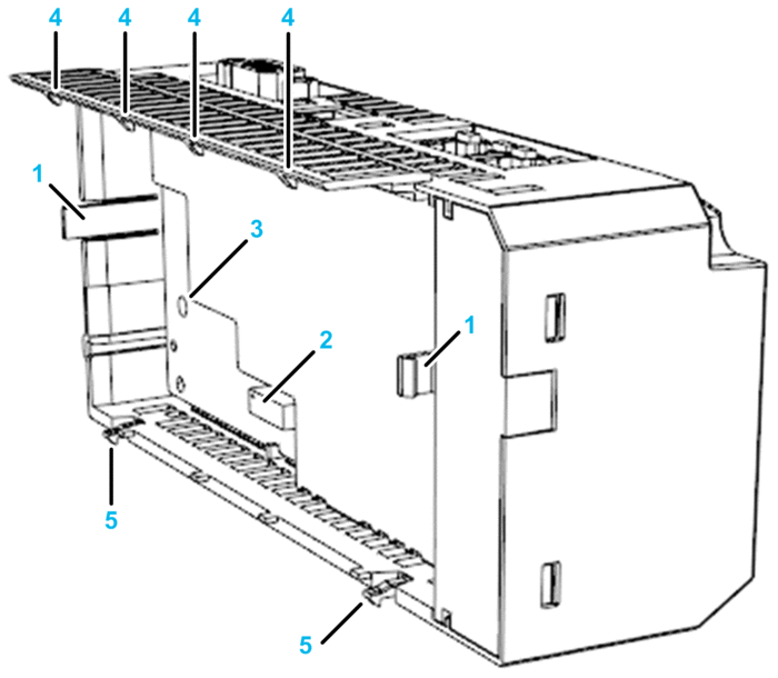
1 locking tabs
2 12-pin female power and communications connector
3 aperture for male-female standoff and ground screw
4 snap connectors on top of processor
5 snap connectors on bottom of processor
The connection points on the I/O base:
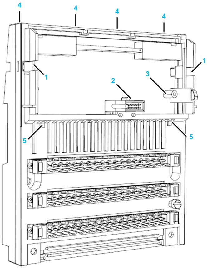
1 locking tab receptacles
2 12-pin male power and communications connector
3 fixed standoff ground nut (not provided on some I/O bases)
4 snap connector receptacles that connect to top of processor (on the back of the I/O base)
5 snap connector receptacles that connect to bottom of processor
You can use the Schneider Electric high vibration assembly kit (170 XTS 120 00) to help stabilize the processors in a high vibration environment.
The 171 CBU 78090, 171 CBU 98090 and 171 CBU 98091 processors do not support the use of option adapters.
Required Tools
The only tool required to install the ground screw is a PZ 2 Phillips head screwdriver. The recommended maximum torque on the ground screw is 0.5 Nm (4.4 in/lb).
Installation
Electrical circuitry on the I/O base may be exposed when a Momentum processor or other adapter is not mounted.
| DANGER | |
|---|---|
Attaching or detaching a Momentum processor with connected communication cables can expose remote electrical ground current.
| DANGER | |
|---|---|
Confirm that the standoff does not touch the electrical components on the processor.
| CAUTION | |
|---|---|
The electrical components of the processor can be damaged by static electricity.
| CAUTION | |
|---|---|
If the parameter is enabled, the processor begins to operate when power is cycled.
| CAUTION | |
|---|---|
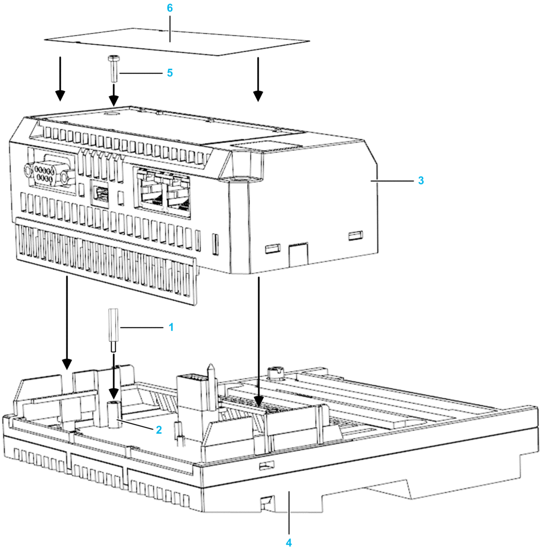
The following diagram indicates the process for assembling the processor and I/O base:
To install the ground screw, follow these steps:
Step |
Action |
|---|---|
1 |
Select a clean environment for the assembly of the components. |
2 |
Remove the power connectors from the I/O base. |
3 |
If the I/O base includes outputs, disconnect the outputs. |
4 |
Disconnect I/O Bus, Ethernet, and serial cables. |
5 |
Install the male-female standoff (1) into the threaded fixed standoff ground-nut assembly (2), located on the I/O module printed circuit board. NOTE: The
male-female standoff is part number 35004788; the fixed standoff ground
nut assembly is part number 35001482.
|
6 |
Snap the processor (3) onto the I/O base (4), gently pressing the locking tabs inward. The locking tabs on each side of the adapter slide inside the I/O base and out through the locking slot. The 12-pin connectors on the 2 units are mated to each other in the process. |
7 |
Use a PZ 2 Phillips head screwdriver to install the standard M3-6 ground screw (5) through the top of the processor. The recommended torque on the ground screw is 0.5 Nm (4.4 in/lb). NOTE: The ground screw is part number V10VC710306.
|
8 |
Insert the label (6) on the front of the processor, sliding the edges of the label under the tabs that hold the label in place. |