Using the High Vibration Assembly Kit
Schneider Electric offers a kit, product 170 XTS 120 00, that you can use to reinforce the CPU and I/O base assembly in high vibration environments.
You can use the specified kit components in the following circumstances:
Kit Components |
Image |
Description |
|---|---|---|
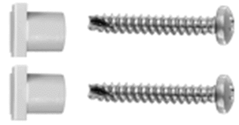
two: screws two: receptacles |

|
Use these components to reinforce the I/O base only when the assembly is mounted on a DIN rail:
NOTE: Do not use these components if your CPU and
I/O base are mounted on a panel.
|
one: 1R connector |

|
Use these components to reinforce the assembly of the CPU to an I/O base that does not include a grille:
|
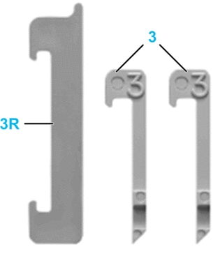
one: 3R connector two: 3 connectors |

|
Use these components to reinforce the assembly of the CPU to an I/O base that includes a grille:
|
For detailed installation instructions, refer to Schneider Electric publication 31001589, which is delivered as part of the 170 XTS 120 00 kit.


