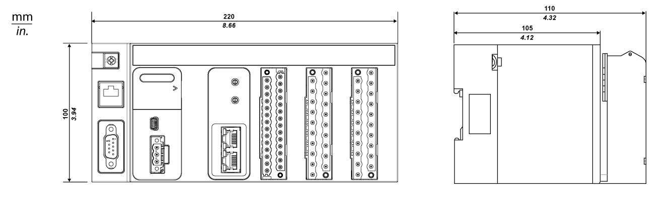
The following figure shows the overall dimensions of the MC80 PLC:
NOTE: The terminal block should be ordered separately. This equipment is "enclosed". It can be installed without any specific protection in areas with restricted access and low pollution levels (not exceeding 2). In other environments, it is recommended to follow rules of installation in a cabinet. Refer to Control Expert documentation, Chapter "General Safety Instructions for the user": 6.2 Environmental conditions.
For compliance to UL (Underwriters Laboratories) requirements, the product is an "open equipment".
For North America systems, the installation and operation of this equipment in an end fire enclosure appropriately rated for its intended environment.
Mounting and Fastening the MC80 PLC
MC80 PLC can be mounted on:
The following are the two types of DIN rails used for mounting MC80 PLC:
The following table describes the procedure for mounting the MC80 PLC on a DIN rail:
|
Step
|
Description
|
Illustration
|
|
1
|
Position the PLC on the DIN rail as indicated in the figure.
|
The following figure shows the mounting on a DIN rail:
|
|
2
|
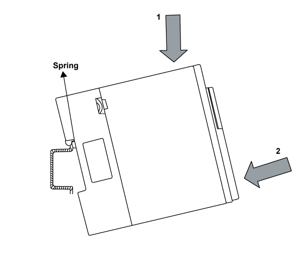
Press down on the MC80 product (1) in order to compress the springs, then tip the product backwards against the rail (2).
|
|
3
|
Release the MC80 product to lock it.
|
To remove the MC80 product, perform the mounting procedure in reverse.
Press down on the product (1) in order to compress the springs, then tip the product forwards to disengage it from the rail (2).
NOTE: To make sure that the PLCs continue to operate correctly when there is severe electromagnetic interference, you must mount the modules on properly grounded metallic mountings.
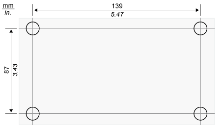
The figure below shows the screw-hole layout for mounting the MC80 PLC on a panel (dimensions in mm/inch):
The diameter of the fastening holes must allow the use of M4 screws.
NOTE: Tighten the screw to help ensure the contact between the BKP and the panel.