|
Analog Input Functional Description
|
|


|
|
|
Analog Input Functional Description
|
|
|
|
|
Function
|
Normal Cycle
|
Fast Cycle
|
|---|---|---|
|
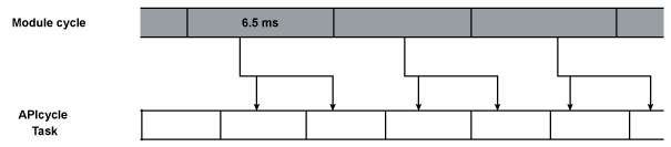
Analog input
|
6.5 ms
|
1.3 ms + (1.3 ms x N)
where N: number of channels in use.
|
|
Designation
|
Description
|
|---|---|
|
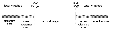
Nominal range
|
Measurement range corresponding to the chosen range
|
|
Upper Tolerance Area
|
Varies between the values included between the maximum value for the range (for instance: +10 V for the ±10 V range) and the upper threshold
|
|
Lower Tolerance Area
|
Varies between the values included between the minimum value for the range (for instance: -10 V for the ±10 V range) and the lower threshold
|
|
Overflow Area
|
Area located beyond the upper threshold
|
|
Underflow Area
|
Area located beyond the lower threshold
|
|
Range
|
Range
|
|||||||||
|---|---|---|---|---|---|---|---|---|---|---|
|
Underflow Area
|
Lower Tolerance Area
|
Nominal Range
|
Upper Tolerance Area
|
Overflow Area
|
||||||
|
Unipolar
|
||||||||||
|
0…10 V
|
-1,400
|
-1,001
|
-1,000
|
-1
|
0
|
10,000
|
10,001
|
11,000
|
11,001
|
11,400
|
|
0...5 V/0...20 mA
|
-5,000
|
-1,001
|
-1,000
|
-1
|
0
|
10,000
|
10,001
|
11,000
|
11,001
|
15,000
|
|
1...5 V/4...20 mA
|
-4,000
|
-801
|
-800
|
-1
|
0
|
10,000
|
10,001
|
10,800
|
10,801
|
14,000
|
|
Bipolar
|
||||||||||
|
±10 V
|
-11,400
|
-11,001
|
-11,000
|
-10,001
|
-10,000
|
10,000
|
10,001
|
11,000
|
11,001
|
11,400
|
|
±5 V, ±20 mA
|
-15,000
|
-11,001
|
-11,000
|
-10,001
|
-10,000
|
10,000
|
10,001
|
11,000
|
11,001
|
15,000
|
|
User
|
||||||||||
|
±10 V
|
-32,768
|
-
|
-
|
-
|
User-defined
|
User-defined
|
-
|
-
|
-
|
32,767
|
|
0...10 V
|
-32,768
|
-
|
-
|
-
|
User-defined
|
User-defined
|
-
|
-
|
-
|
32,767
|
|
Type of Range
|
Display
|
|---|---|
|
Unipolar range
0…10 V, 0…5 V, 1…5 V, 0...20 mA, 4…20 mA
|
From 0...10,000 (0% at +100%)
|
|
Bipolar range
±10 V, ±5 V, ±20 mA
|
From -10,000…10,000 (-100% at +100%)
|
|
Desired Efficiency
|
Required Value
|
Corresponding α
|
Filter Response Time at 63%
|
Cut-off frequency (Hz)
|
|---|---|---|---|---|
|
No filtering
|
0
|
0
|
0
|
-
|
|
Smooth filtering
|
1
|
0.750
|
4* T
|
0.040/T
|
|
2
|
0.875
|
8* T
|
0.020/T
|
|
|
Average filtering
|
3
|
0.937
|
16* T
|
0.010/T
|
|
4
|
0.969
|
32* T
|
0.005/T
|
|
|
High filtering
|
5
|
0.984
|
64* T
|
0.0025/T
|
|
6
|
0.992
|
128* T
|
0.0012/T
|
 DANGER DANGER |
|
HAZARD OF ELECTRIC SHOCK, EXPLOSION, OR ARC FLASH
While mounting / removing the modules:
Failure to follow these instructions will result in death or serious injury.
|
 WARNING WARNING |
|
UNEXPECTED EQUIPEMENT OPERATION
Failure to follow these instructions can result in death, serious injury, or equipment damage.
|
|
DANGER |
|
HAZARD OF ELECTRIC SHOCK
Sensors and other peripherals may be connected to a grounding point some distance from the module. Such remote ground references may carry considerable potential differences with respect to local ground. Ensure that:
Failure to follow these instructions will result in death or serious injury.
|
 CAUTION CAUTION |
|
UNEXPECTED BEHAVIOR OF APPLICATION
Follow these instructions to reduce electromagnetic perturbations:
Electromagnetic perturbations may lead to an unexpected behavior of the application.
Failure to follow these instructions can result in injury or equipment damage.
|
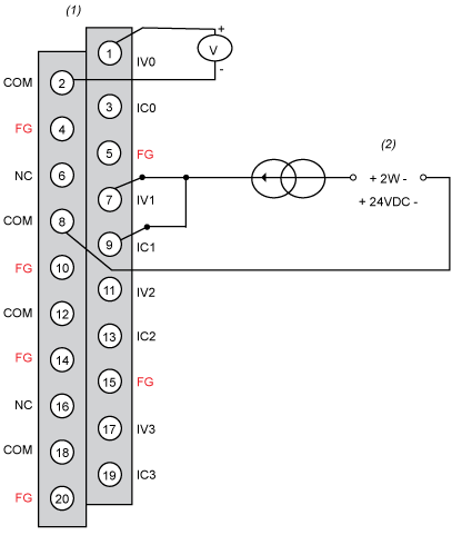
IVx:pole input for channel x
COM:common pin for each channel
ICx:current reading resistor + input
FGfunctional ground
|
I/O Function
|
Reference Number
|
|---|---|
|
AnaIog Input function
|
BMX FTB 2000
BMX FTB 2010
BMX FTB 2020
|

|
Status LEDs AMI Function
|
Function Status
|
|---|---|
|
IN Channel
|
|
|
ON
|
Operating normally
|
|
OFF
|
Module is running with channels in stopped state
|
|
OFF
|
Module is inoperative or turned off
|
|
OFF
|
Module not configured or channel configuration in progress
|
|
OFF
|
Internal error in module
|
|
OFF
|
Not configured
|
|
BLK
|
Range under/overflow error
|
|
FLK
|
Sensor link error
|
|
Legends
|
|
|
ON
|
LED is turned on
|
|
OFF
|
LED is turned off
|
|
FLK (Flickering)
|
The LED is turned on for 50 ms then turned off for 50 ms, and then repeat
|
|
BLK (Blinking)
|
The LED is turned on for 200 ms then turned off for 200 ms, and then repeat
|
