Grounding of PLC
 
Description
The grounding of MC80 PLC is important to avoid electric shock and the configuration involves the grounding screw and power supply terminal.
WARNING
UNINTENDED EQUIPMENT OPERATION
Tighten the clamping screws of the modules. A break in the circuit could lead to an unexpected behavior of the system.
Failure to follow these instructions can result in death, serious injury, or equipment damage.
Grounding the Protective Earth (PE) terminal of PLC
Protective grounding must be performed by connecting the grounding screw located on the left-hand side of the product to the earth of installation.
Two cables of ø3 mm maximum can be connected using grounding screw.
Grounding the Power Supply Terminal (FG)
The Functional Ground (FG) located on the power supply must be connected to the earth of installation in one of the following two ways:
DANGER
HAZARD OF ELECTRIC SHOCK
Power supply terminal must be grounded. Do not connect anything else to the power supply ground.
Failure to follow these instructions will result in death or serious injury.
Representations
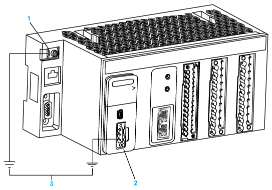
The following figure shows the ground connection between grounding screw and FG of power supply using two independent ground cables.
1 
Grounding Screw (Maximum tighten torque: 1.5 N•m (1.1 lb-ft))
2 
Power Supply Terminal Block
3 
Earth of installation
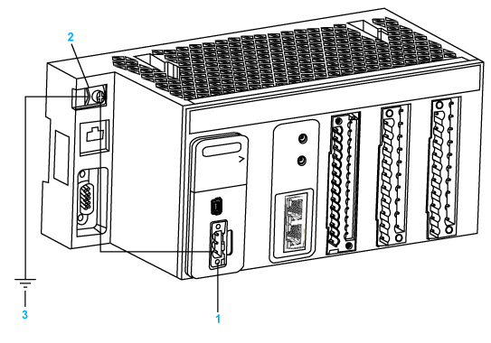
The following figure shows the ground connection between grounding screw and FG of power supply.
1 
Power Supply Terminal Block
2 
Grounding Screw (Maximum tighten torque: 1.5 N•m (1.1 lb-ft))
3 
Earth of installation
DANGER
HAZARD OF ELECTRIC SHOCK
Use only cables with ring or spade lugs to ensure connection to ground. Ensure grounding hardware is tightened properly.
Failure to follow these instructions will result in death or serious injury.
Grounding Bar
To guarantee protection against electromagnetic interferences, the cable shielding is directly connected to the ground.
NOTE: The cable shielding is not connected to the module shielding.
This connection can be made using any method but a protection bar is provided in order to facilitate the set up.
A protection bar is used in two cases:
The STB grounding bar references are listed below:
Reference
Description
STBXSP3000
SHD KIT BRACKETS AND BAR
STBXSP3020
QTY10 SHD KIT SIZE 2 WIRE CLAMP (for fastening analog and counting modules connection cables)
Each kit includes the following components:
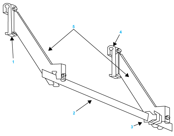
The following figure shows a grounding bar fastened to DIN rail Hook:
1 
DIN rail Hook
2 
Grounding bar
3 
FG grounding clamp
4 
DIN rail Hook
5 
Side brackets