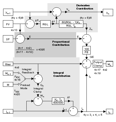
The elements in the block diagram have the following meaning:
|
Element
|
Meaning
|
|
E
|
detected error, expressed in raw analog units
|
|
SP
|
set point, in the range 0 ... 4095
|
|
PV
|
process variable, in the range 0 ... 4095
|
|
x
|
filtered PV
|
|
K2
|
integral mode gain constant, expressed in 0.01 min-1
|
|
K3
|
derivative mode gain constant, expressed in hundredths of a minute
|
|
RGL
|
rate gain limiting filter constant, in the range 2 ... 30
|
|
Ts
|
solution time, expressed in hundredths of a second
|
|
PB
|
proportional band, in the range 5 ... 500%
|
|
bias
|
loop output bias factor, in the range 0 ... 4095
|
|
M
|
loop output
|
|
GE
|
gross error, the proportional-derivative contribution to the loop output
|
|
Z
|
derivative mode contribution to GE
|
|
Qn
|
unbiased loop output
|
|
F
|
feedback value, in the range 0 ... 4095
|
|
I
|
integral mode contribution to the loop output
|
|
Ilow
|
anti-reset-windup low SP, in the range 0 ... 4095
|
|
Ihigh
|
anti-reset-windup high SP, in the range 0 ... 4095
|
|
K1
|
100/PB
|
NOTE: The integral mode contribution calculation actually integrates the difference of the output and the integral sum. This is effectively the same as integrating the error.
With proportional-only control (P), you can calculate the manipulated variable by multiplying error by a proportional constant, K1, then adding a bias. See
Formula.
However, process conditions in most applications are changed by other system variables so that the bias does not remain constant; the result is offset error, where PV is constantly offset from the SP. This condition limits the capability of proportional-only control.
NOTE: The value in the integral term (in words 4y + 3, 4y + 4, and 4y + 5) is always used, even when the integral mode is not enabled. Using this value is necessary to preserve bumpless transfer between modes. If you wish to disable bumpless transfer, these three words must be cleared.
In manual mode setpoint changes will not take effect unless the above three words are cleared and the mode is switched back to automatic. The transfer will not be bumpless.
Proportional-Integral Control
To remove this offset error without forcing you to manually change the bias, an integral function can be added to the control equation. See
Formula.
Proportional-integral control (PI) removes offset by integrating E as a function of time. K1 is the integral constant expressed as rep/min. As long as E ≠ 0, the integrator increases (or decreases) its value, adjusting Mv. This continues until the offset error is removed.
Proportional-Integral-Derivative Control
You may want to add derivative functionality to the control equation to minimize the effects of frequent load changes or to override the integral function in order to get to the SP condition more quickly. See
Formula.
Proportional-integral-derivative (PID) control can be used to save energy in the process or to avoid a sudden, unexpected change in process flow. K3 is the derivative time constant expressed as min. DPV is the change in the process variable over a time period of Δt.
