|
Wiring and installation recommendations for the model TBX AMS 620
|
|
|
(Original Document)
|
|
Precautions to take
|
||
|---|---|---|
|
Type of conductors
|
Use screened twisted pairs, with a minimum conductor cross-section of 0.28 mm2.
|
|
|
Cable screening
|
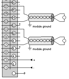
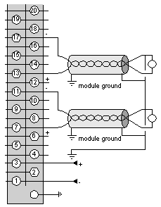
Connect the cable screening to the shortest TBX module ground on the TBX GND 015 grounding strip.
|
|
|
Arrangement of the conductors in cables
|
Multipair cables can be rearranged for signals of a similar type which have the same reference to ground.
|
|
|
Cable routing
|
Keep the measurement wires separate from the discrete I/O cables (in particular from relay outputs) and from power cables.
|
|
|
Preactuator and sensor reference to ground
|
The TBX AMS 620 module has 6 inputs which are not isolated from each other but which are isolated from the PLC bus, and 2 outputs which are isolated from each other and from the PLC bus.
The sensor cold points are connected to each other internally by the Com terminals.
To ensure good immunity to high frequency interference, a 4.7 nF capacitor is connected between the channel voltage and the ground.
To ensure correct operation of the analog measurement system, the following precautions must be taken:
Note: There are no technical restrictions in referencing the preactuators to ground. However, for safety reasons, it is advisable to avoid using a ground voltage which is some distance from the terminal, as this ground voltage may be very different from the nearby ground voltage. Distributed I/O modules minimize this risk as they are usually close to the process.
|
 |
|
Sensor reference to ground
|
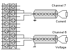
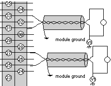
If the following characteristics are respected, then each sensor can be assigned a voltage rate according to ground:
|
 |
|
Preactuator reference to ground
|
|
 |
|
Preactuator reference to ground (cont.)
|
|
 |