|
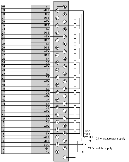
Connecting the module TBX DSS 16C22
|
|


|
(Original Document)
|
|
Connecting the module TBX DSS 16C22
|
|
|
(Original Document)
|
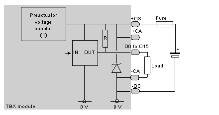
1Guaranteed threshold for monitored voltage OK: > 18 V, guaranteed threshold for monitored voltage faulty: < 14 V.