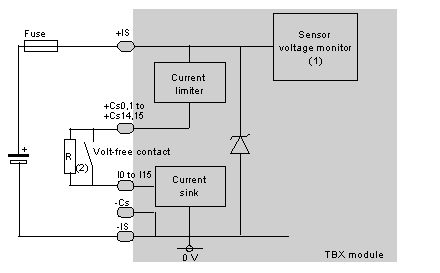
The following illustration shows the circuit diagram for a wiring check input.
1
Guaranteed threshold for monitored voltage OK: > 18 V, guaranteed threshold for monitored voltage faulty: < 14 V.
2
Resistance R for a dry contact or a 3-wire proximity sensor enables the input wiring check to be used.
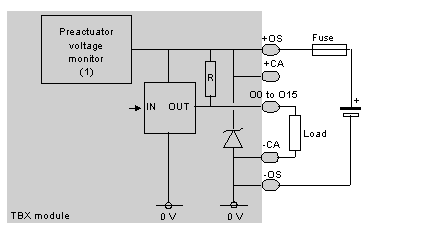
The following illustration shows the circuit diagram for a transistor output.
1
Guaranteed threshold for monitored voltage OK: > 18 V, guaranteed threshold for monitored voltage faulty: < 14 V.
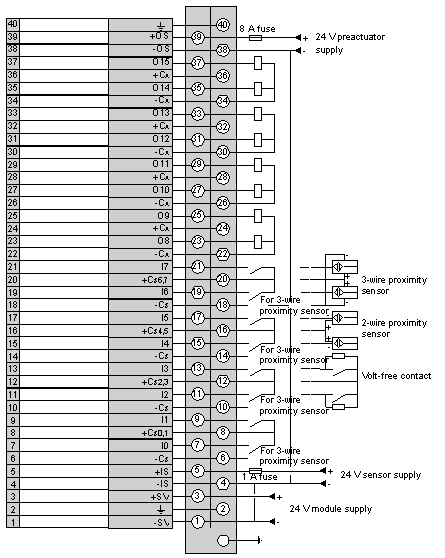
The following diagram illustrates the wiring of the terminal.
NOTE: a quick blow 1 A external fuse must be wired to the sensor power supply and a quick blow 8 A external fuse must be wired to the preactuator power supply.