|
Connecting the module TBX EEP 1622
|
|
|
(Original Document)
|

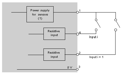
1Power supply to the sensors is provided via the module.

 WARNING WARNING |
|
SHORT CIRCUIT - LOSS OF PROOF
Do place the blanking plugs on slots where channels are not in use in order to retain the IP65 dust and damp proof protection.
Failure to follow these instructions can result in death, serious injury, or equipment damage.
|