|
Connecting the TBX ESP 08C22 Module
|
|
|
(Original Document)
|

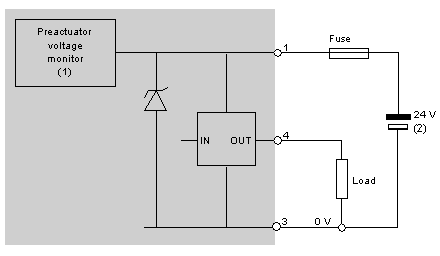
1Guaranteed threshold for monitored voltage OK: > 18 V, guaranteed threshold for monitored voltage faulty: < 14 V.
2This power supply is provided via the TBX BAS 10 connector.

|
Number of channels
|
Maximum output current per module
|
|---|---|
|
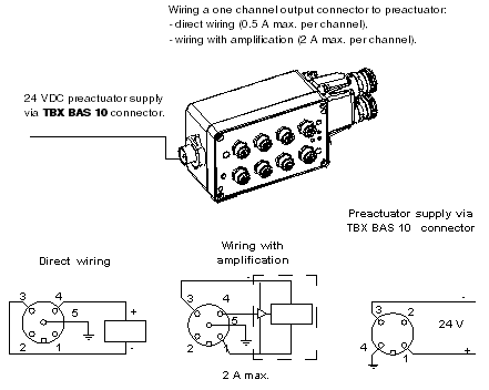
8 direct channels
|
8 x 0.5 A = 4 A
|
|
6 direct channels
2 amplified channels
|
6 x 0.5 A + 2 x 1 A = 5 A
|
|
7 direct channels
1 amplified channel
|
7 x 0.5 A + 1 x 2 A = 5.5 A
|
 WARNING WARNING |
|
SHORT CIRCUIT - LOSS OF PROOF
Do place the blanking plugs on slots where channels are not in use in order to retain the IP65 dust and damp proof protection.
Failure to follow these instructions can result in death, serious injury, or equipment damage.
|

|
Step
|
Action
|
|---|---|
|
1
|
Strip the cable back up to a maximum of 2 cm.
|
|
2
|
Mount the connector as follows:
|
|
3
|
Feed the cable through the part which has been assembled (cable gland).
|
|
4
|
Attach the wires to the terminals of the second part (+ on terminal 1, - on terminal 3, protective ground on terminal 4).
Caution: if the 24V module supply and 24V preactuator supply are not isolated, a reversion of polarity may destroy the module.
|
|
5
|
Place part F over part H.
|
|
6
|
Attach the cable in the cable clamp F, using part G and the two screws provided.
|
|
7
|
Fit both parts of the connector together and tighten the cable gland D.
|