|
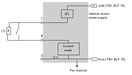
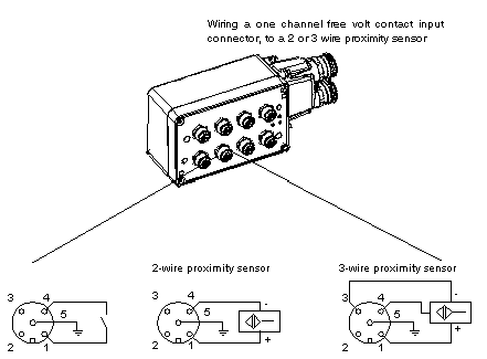
Connecting the module TBX EEP 08C22
|
|
|
(Original Document)
|

1Resistance R for a dry contact or a 3-wire proximity sensor, enables the input wiring check to be used.
2Power supply to the sensors is provided via the module.

 WARNING WARNING |
|
SHORT CIRCUIT - LOSS OF PROOF
Do place the blanking plugs on slots where channels are not in use (tightening torque of cable glands: 1 Nm), in order to retain the IP65 dust and damp proof protection.
Failure to follow these instructions can result in death, serious injury, or equipment damage.
|