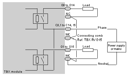
The following illustration shows the circuit diagram of a relay output (normally open contacts).
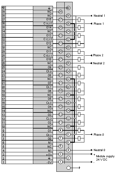
The illustration below provides an example of a wiring diagram: The module outputs organized into two groups by the user have separate power supplies (outputs 0 to 9, outputs 10 and 11 and outputs 12 to 15).
The NC terminals are not wired within the modules, but are used to distribute the power supply neutral to the various loads. For this purpose, use connecting combs, reference
TBX RV 015.
A connecting comb is also used to connect the relay commons (C0,1, C2,3,...) with the supply phase.
The following diagram illustrates the wiring of the terminal.

