|
Configuring dip-switch SW1 (IP20 discrete base units)
|
|
|
(Original Document)
|
|
Leakage current (natural or induced)
|
SW1 position
|
|---|---|
|
The sensor has a leakage current between 0.45 mA and 1 mA.
|
ON
|
|
The sensor has a leakage current between 1 mA and 1.8 mA.
|
OFF
|
|
Type of sensor
|
SW1
|
External adaptation
|
Illustration
|
|---|---|---|---|
|
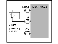
2 wire proximity sensor with leakage current between 0.45 mA and 1 mA.
|
ON
|
No adaptation.
|
 |
|
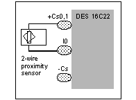
2-wire proximity sensor with leakage current between 1 mA and 1.8 mA.
|
OFF
|
No adaptation.
|
 |
|
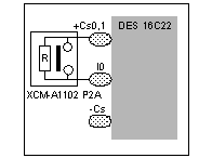
Limit switch reference XCM‐A1102 P2A.
|
OFF
|
No adaptation (Limit switch 2 fitted with 15 kΩ resistor connected to the open contact.).
|
 |
|
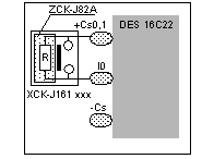
Limit switch reference XCK‐J161••• fitted with a ZCK‐J82A module.
|
OFF
|
No adaptation.
|
 |
|
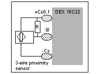
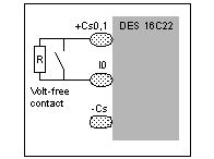
Volt free contact or 3 wire proximity sensor with induced leakage current between 0.45 mA and 1 mA.
|
ON
|
Installation of a 33 kΩ +-5 % resistor in parallel with the 24 V sensor terminals.
|
  |
|
Volt free contact or 3 wire proximity sensor with induced leakage current between 1 mA and 1.8 mA.
|
OFF
|
Installation of a 15 kΩ +-5 % resistor in parallel with the 24 V sensor terminals.
|