The various remote I/O devices are connected to each other and to the PLC by daisy chaining or tap links, over the field bus.
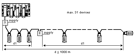
A Fipio bus segment (which can be up to 1000 meters in length) provides 32 connection points to which 31 TBX devices may be connected (one connection point at address 0 is reserved for the PLC).
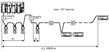
The use of repeaters enables up to 15 bus segments to be connected together, so that TBX devices can be connected over a maximum distance of 15000 meters.
Using several bus segments gives a maximum of 64 connection points. Thus it is possible to connect 62 modular or (IP65) TBX modules, (in addition to point 0 reserved for PLC connection, and point 63 which is used to connect a terminal).
The following drawing shows the connection between TBX IP20 modules and the PLC via a single Fipio bus segment.
The following drawing shows the connection between TBX IP20 modules and the PLC via several Fipio bus segments.
1
Fipio bus segment (15 x 1000 m segments maximum).
2
Repeater (14 maximum).
The following drawing shows the connection between TBX IP65 modules and the PLC via a single Fipio bus segment.
3
TBX FP ACC10 branch box.
The following drawing shows the connection between TBX IP65 and IP20 modules and the PLC via several Fipio bus segments.
d1
Maximum length of the 24 VDC drop and power cable. Cable reference number: TSX FP CF100,TSX FP CF200,TSX FP CF500.
2
Repeater (14 maximum).
3
TBX FP ACC10 branch box. 


