|


|
(Original Document)
|
|
|
(Original Document)
|
|
Step
|
Action
|
|
|---|---|---|
|
1
|
Attach the TBX to its support.
|
|
|
2
|
Prepare the TBX BLP 10 connector (wiring). The installation is described in stages 3 to 9.
|
|
|
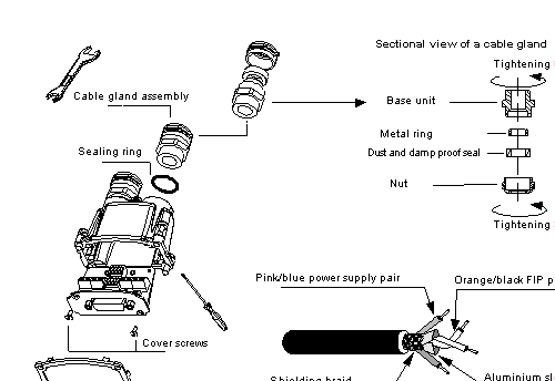
3
|
Presentation of the product.
 |
|
|
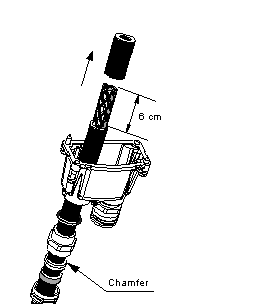
4
|
Remove the cable gland and pass the cable through it (take care to ensure that the chamfer on the metal ring is facing upwards). Strip the cable sheath to a length of 6 cm.
|
 |
|
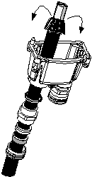
5
|
Fold back the shielding braid on the cable sheath; if necessary, undo the braid.
|
 |
|
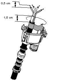
6
|
Strip the conductors by 0.5 cm, and leave 1.5 cm of sleeve.
Hold the braid down on the cable sheath using adhesive tape.
|
 |
|
7
|
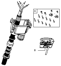
It is preferable to use the wiring accessories (A) to connect the conductors.
There are two possible connection methods: by extension or tap-off.
Set the address using the switches (B).
|
 |
|
8
|
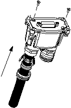
Replace the card in the unit, then close the unit using the two screws. Remove the adhesive tape holding the braid and pass the metal ring under the braid. Check that the braid does not protrude beyond the cable gland (to ensure dust and damp proofing) and position the seal under the metal ring.
|
 |
|
9
|
Tighten the cable gland nut to the tightening torque given at step 3.
|
 |
|
10
|
Attach the TBX BLP 10 connector to the module and connect the green/yellow wire to the screw clamp on the TBX BLP 10.
|
|
|
11
|
Switch on.
All the lights flash during the self-test phase of the communication module. Following the self-test, the RUN LED is permanently on, and where there is no connection to the Fipio bus the ERR lamp flashes. The channel display lamps indicate channel status together with any faults (short-circuit or open circuit, etc.).
The I/O should be checked when the module is connected to the Fipio bus and when the bus is operational. The connection point configuration is sent automatically to the module from the PLC configuration.
|
|
|
12
|
Maintenance:
|
|
