It is connected on 8 0.5 A transformer outputs of a IP20 module, and enables the following to be simulated:
The red LEDs indicate the state of the outputs when simulating the presence of loads.
The transistor output simulator is fixed directly on the screw terminal of the TBX module (
terminals O0 to O7, O8 to O15 or I/O8 to I/O15). The common wire (white) must be connected to a -Cs, -Csm,n+1 or -C (0V)
terminal.
To simulate all the TBX module outputs (O0 to O15), two transistor output simulators are required:
NOTE: For TBX mixed modules, the transistor output simulator is used with an input simulator.
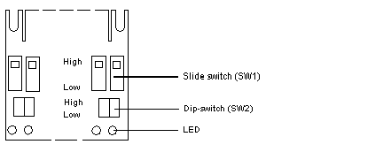
The following diagram shows the switches that can be used with transistor output simulators.
Description: SW2 in upper position
SW2 in upper position: no simulation of load present.
Description: SW2 in lower position
SW2 in lower position: simulation of load present.
