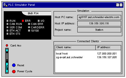
The dialog box is shown if the simulator is simulating a CPU from the Modicon M340 family.
Representation of the dialog box:
The virtual CPU front plate shows the current state of the CPU in a multi-line display using combinations of the RUN and ERR LEDs:
|
RUN LED
|
ERR LED
|
The simulated CPU is in state...
|
Meaning
|
|
off
|
flashing
|
NOCONF (no configuration)
|
No user project loaded or the loaded project is invalid.
|
|
flashing
|
off
|
IDLE
|
The project loaded on the CPU has not been started or reset with the Reset button.
|
|
flashing
|
off
|
STOPPED
|
No project is running. However, the loaded project was in RUN state at least once.
|
|
on
|
off
|
RUN
|
A project with at least one task is running.
|
|
off
|
flashing
|
HALT
|
An error has occurred in the project. The simulated CPU must be reinitialized or reset using the Reset button.
|
|
off
|
on
|
ERROR
|
An unrecoverable detected error has occurred in the project. This means communication is no longer possible. The simulated CPU must be reset using the Reset button.
|
When data is being exchanged between Control Expert (or other clients) and the simulator, the SER COM LED is flashing.
The CARDERR LED is ON if a problem occurs during card access or if the memory card is removed.
The I/O, CAN RUN, CAN ERR, ETH ACT, ETH STS, and 10/100 LEDs are not supported by the simulator.
The Card Acc LED is on when the card is accessible.
The following features of a memory card can be simulated for the
Modicon M340 CPU:
With this button, you can reset the simulated CPU. This corresponds to a cold start of the CPU where the connection between Control Expert and the simulator is broken, project variables are reset and the simulator goes in RUN (if auto start is activated) or in STOP (if auto start is deactivated)).
With this button, you execute a power cycle (power off/ power on) for the simulated CPU. This corresponds to a warm start of the CPU (the connection between Control Expert and the simulator is broken and the current project variables remain).
A power cycle corresponds to a power off and power on of a real power supply.
Dialog box fields:
Host PC name:
DNS name of the host PC for the simulator. If the PC has multiple network cards, only the first is shown.
Host IP address:
TCP/IP address of the host PC for the simulator. If the PC has multiple network cards, only the first is shown.
Project name:
Name of the project loaded in the simulator.
