Description of Hot Standby Quantum System Words %SW60 to %SW69
Original instructions
Detailed Description
Description of the Qunatum Hot standby system words %SW60 to %SW69:
Word
Symbol
%SW60
HSB_CMD
Function
Quantum Hot Standby command register
Initial State
0
Different bits meaning of the word %SW60:
  • %SW60.0 = 1 invalidates the commands entered in the display (keypad).
  • %SW60.1:
    • 0 sets PLC A to OFFLINE mode.
    • 1 sets PLC A to ONLINE mode.
  • %SW60.2:
    • 0 sets PLC B to OFFLINE mode.
    • 1 sets PLC B to ONLINE mode.
    NOTE: The primary CPU controller goes to RUN offline only if the secondary CPU is RUN standby.
    At startup of the secondary PLC, the secondary CPU goes to online mode (RUN standby) only if both bits %SW60.1 and %SW60.2 are set to 1 (regardless of A/B assignment).
    If bits %SW60.1 and %SW60.2 are set to 0 simultaneously, a switchover occurs:
    • Primary controller goes RUN offline, and
    • Standby controller now operates as RUN primary.
    To finish the switchover, bits %SW60.1 and %SW60.2 must be set back to 1. This makes the offline CPU going back to online mode (Run standby).
    The OFFLINE/ONLINE mode controlled by the %SW60.1 and %SW60.2 bits is not linked to the LCD Keypad ONLINE/OFFLINE mode.
  • %SW60.3:
    • 0 If an application mismatch is detected, standby CPU is forced to OFFLINE mode.
    • 1 standby CPU operates normally even if a mismatch occurs.
  • %SW60.4:
    • 0 authorizes an update of the firmware only after the application has stopped.
    • 1 authorizes an update of the firmware without the application stopping.
  • %SW60.5:
    • 0 no action (default).
    • 1 request for an application transfer from the primary to the standby.
    Take care that modifying %SW60.5 by application and requiring simultaneously a transfer by Keypad, could lead to some issues (no transfer or transfer retry).
  • %SW60.8:
    • 0 address-switch on Modbus port 1 during a primary swap.
    • 1 no address-switch on Modbus port 1 during a primary swap.
%SW60
HSB_CMD
Function
Quantum Hot Standby command register
Initial State
0
Continued:
  • %SW60.9:
    • 0 address-switch on Modbus port 2 during a primary swap.
    • 1 no address-switch on Modbus port 2 during a primary swap.
  • %SW60.10:
    • 0 address-switch on Modbus port 3 during a primary swap.
    • 1 no address-switch on Modbus port 3 during a primary swap.
%SW61
HSB_STS
Function
Quantum Hot Standby status register
Initial State
0
Meaning of the different bits of the word %SW61:
  • %SW61.0 and %SW61.1 PLC operating mode bits:
    • %SW61.1 = 0, %SW61.0 = 1: OFFLINE mode.
    • %SW61.1 = 1, %SW61.0 = 0: primary mode.
    • %SW61.1 = 1, %SW61.0 = 1: secondary mode (Standby).
  • %SW61.2 and %SW61.3 operating mode bits from the other PLC:
    • %SW61.3 = 0, %SW61.2 = 1: OFFLINE mode.
    • %SW61.3 = 1, %SW61.2 = 0: primary mode.
    • %SW61.3 = 1, %SW61.2 = 1: secondary mode (Standby).
    • %SW61.3 = 0, %SW61.2 = 0: The remote PLC is not accessible (switched off, no communication).
  • %SW61.4:
    • 0: The applications are identical on both PLCs.
    • 1: The applications are not identical on both PLCs.
  • %SW61.5:
    • 0: The PLC is used as unit A.
    • 1: The PLC is used as unit B.
  • %SW61.6 indicates if the CPU-sync link between the 2 PLCs is valid:
    • 0: The CPU-sync link is operating properly. The contents of bit 5 are significant.
    • 1: The CPU-sync link is not valid. In this case, the contents of the bit 5 is not significant because the comparison of the 2 MAC addresses cannot be performed.
  • %SW61.7:
    • 0: the operating system versions are the same in both the primary and standby: CPUs, Ethernet copro, CRPs.
    • 1: the 2 PLCs have at least one operating system version mismatch between the primary and standby: CPUs, Ethernet copro, CRPs.
      For details about the component mismatches, refer to %SW69.
  • %SW61.8:
    • 0: same copro OS versions.
    • 1: different copro versions.
  • %SW61.12:
    • 0: Information given by bit 13 is not relevant.
    • 1: Information given by bit 13 is valid.
%SW61
HSB_STS
Function
Quantum Hot Standby status register
Initial State
0
Continued:
  • %SW61.13:
    • 0: NOE address set to IP.
    • 1: NOE address set to IP + 1.
  • %SW61.15:
    • 0: Hot Standby not activated.
    • 1: Hot Standby activated.
%SW62
HSBY_REVERSE0
%SW63
HSBY_REVERSE1
%SW64
HSBY_REVERSE2
%SW65
HSBY_REVERSE3
Function
Hot Standby reverse transfer word
Initial State
0
These 4 words are modified in the Hot Standby MAST task in first section of the user application program.
They are then transferred automatically from the standby processor to update the primary PLC.
They may be read on the primary PLC and used in the Hot Standby application.
%SW68
HSBY_APP_STATUS
Function
Hot Standby application status
Initial State
0
%SW68.1: Applications:
  • 0: The applications are identical on both PLCs.
  • 1: The applications are not identical on both PLCs.
%SW68.4: Init values:
  • 0: The Init values are the same on both PLCs.
  • 1: The Init values are not the same on both PLCs.
    In this case, verify the optic fiber cables.
%SW69
HSBY_FW_MISMATCH
Function
Hot Standby firmware mismatch register
Initial State
0
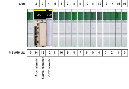
Each bit of this word indicates the results of the comparison of firmware levels between primary and standby main rack slots that contain the same CPU, copro or Ethernet CRP. This word can handle the large 16-slots racks if smaller racks are used the excess bits are not valid. For example, if 8-slot racks are used, only the first 8 bits of the word are valid.
For the 16 bits:
  • If a bit = 0, the primary and standby components have the same firmware versions.
  • If a bit = 1, the primary and standby components have different firmware versions.
NOTE: Bits 0 to 15 correspond to rack positions 16 to 1.