|
IEC 60870-5-101 Slave RTU Protocol Parameters
|
|
|
Original instructions
|
|
Parameter
|
Value scope
|
Default value
|
Description
|
|---|---|---|---|
|
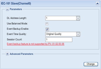
DL Address Length
|
1...2
|
1
|
indicates the bytes used for data link address
|
|
Use Balanced Mode
|
check box
|
unchecked
|
indicates the usage of balanced or unbalanced mode
|
|
Event Backup Enable
|
check box
|
unchecked
|
indicates whether to backup event on loss of power
|
|
Event Time Quality
|
Invalid, Original Quality
|
Original Quality
|
When restoring backup events after power restoration, the time quality is forced to
NOTE: The box Event Backup Enable must be checked beforehand |
|
Session Count
|
1...32
|
1
|
indicates the maximum number of sessions on the channel
|
|
Parameter
|
Value scope
|
Default value
|
Description
|
|---|---|---|---|
|
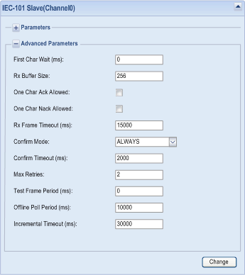
First Char Wait (ms)
|
0...65535
|
0
|
indicates the minimum time between reception and transmission
|
|
Rx Buffer Size
|
0...256
|
256
|
indicates the receive buffer size of serial port (bytes)
|
|
One Char Ack Allowed
|
check box
|
unchecked
|
allows transmission of one-character E5 instead of the fixed-length ACK message
|
|
One Char Nack Allowed
|
check box
|
unchecked
|
allows transmission of one-character response instead of the fixed-length NACK message, when no response data is available
|
|
Rx Frame Timeout (ms)
|
0...4294967295
|
15000
|
indicates the timeout of waiting for a complete frame after the receiving frame synchronization
|
|
Confirm Mode
|
NEVER/SOMETIMES/ALWAYS
|
ALWAYS
|
specifies when to request the link layer confirmation for variable sized frames that contain user data, which is not transmitted to the broadcast address
|
|
Confirm Timeout (ms)
|
0...4294967295
|
2000
|
indicates the maximum waiting time for link level confirmation, if requested
|
|
Max Retries
|
0...255
|
2
|
indicates the retry count of the link layer confirmation timeouts
|
|
Test Frame Period (ms)
|
0...4294967295
|
0
|
specifies the period for transmitting the verification message, to prove that the remote device is still online in the balance mode
|
|
Offline Poll Period (ms)
|
0...4294967295
|
10000
|
specifies the period to re-establish transfer of an offline session
|
|
Incremental Timeout (ms)
|
0...4294967295
|
30000
|
indicates the incremental application layer timeout
|
|
Parameter
|
Value scope
|
Default value
|
Description
|
|---|---|---|---|
|
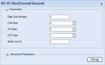
Data Link Address
|
0...65535
|
3
|
indicates bytes for the data link address
|
|
CAA Size
|
1...2
|
2
|
specifies bytes for common address of Application Specific Data Unit
|
|
IOA Size
|
1...3
|
2
|
specifies bytes of IOA
|
|
COT Size
|
1...2
|
1
|
specifies bytes of COT
|
|
Sector Count
|
1...5
|
1
|
indicates sectors for this session
|
|
Parameter
|
Value scope
|
Default value
|
Description
|
|---|---|---|---|
|
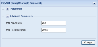
Max ASDU Size
|
0...252
|
252
|
indicates the maximum size of an Application Specific Data Unit
|
|
Max Poll Delay (ms)
|
0...4294967295
|
20000
|
indicates the maximum time between link polls before the unbalanced slave is declared offline
|
|
Parameter
|
Value scope
|
Default value
|
Description
|
|---|---|---|---|
|
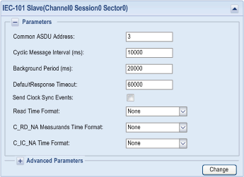
Common ASDU Address
|
1...65535
|
3
|
indicates the common address of ASDU, 65535 is broadcast address
|
|
Cyclic Message Interval (ms)
|
0...4294967295
|
10000
|
specifies the number of milliseconds between cyclic updates
|
|
Background Period (ms)
|
0...4294967295
|
20000
|
specifies the period to generate background scan data on this sector
|
|
Default Response Timeout (ms)
|
0...4294967295
|
60000
|
indicates the default timeout for the confirmation of request
|
|
Send Clock Sync Events
|
check box
|
unchecked
|
controls if spontaneous clock synchronization events are transmitted to the master. The time format is CP24
|
|
Read Time Format
|
None/ CP24/ CP56
|
None
|
specifies the completeness time format for respond to C_RD_NA
|
|
C_RD_NA Measurands Time Format
|
None/ CP24/ CP56
|
None
|
specifies the time format for respond to C_RD_NA
|
|
C_IC_NA Time Format
|
None/ CP24/ CP56
|
None
|
specifies the time stamp format in response of C_IC_NA
|
|
Parameter
|
Value scope
|
Default value
|
Description
|
|---|---|---|---|
|
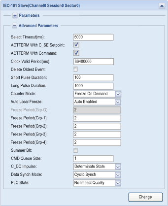
Select Timeout (ms)
|
0...4294967295
|
5000
|
specifies the period after which a previously received selection is timed-out. An execute command must be received before the timeout in order to be valid.
|
|
ACTTERM with CSE Setpoint
|
check box
|
checked
|
specifies if ACT TERM is transmitted upon completion of the set point commands: C_SE_NA, C_SE_NB, C_SE_NC, C_SE_TA, C_SE_TB, C_SE_TC
|
|
ACTTERM with Command
|
check box
|
checked
|
specifies if ACT TERM is transmitted upon completion of commands, other than the set point commands.
|
|
Clock Valid Period (ms)
|
0...4294967295
|
86400000
|
specifies the period for which the system clock remains valid after a clock synchronization. If this period expires without a clock synchronization, all times are reported invalid.
|
|
Delete Oldest Event
|
check box
|
unchecked
|
specifies if the oldest event is removed from the event queue when buffer is full and a new event comes.
Checked:
Remove the oldest event.
Unchecked:
Ignore the new event.
|
|
Short Pulse Duration
|
0...4294967295
|
100
|
specifies the width of the pulse in milliseconds
|
|
Long Pulse Duration
|
0...4294967295
|
1000
|
specifies the width of the pulse in milliseconds
|
|
Counter Mode
|
Freeze On Demand
Local Freeze Only
Local Freeze and Reset
|
Freeze On Demand
|
specifies the mode of freezing counter
To support Mode A or Mode B, select either Local Freeze Only or Local Freeze and Reset.
To support Mode C or Mode D, select Freeze On Demand.
|
|
Auto Local Freeze (1)
|
Auto Enabled
Control by App
|
Auto Enabled
|
specifies the local freeze start and stop conditions
Behavior:
Auto Enabled:
Local freeze starts automatically after the module’s startup or restart.
Control by App:
Local freeze is configured by CPU application. Use CUSTOM_CMD data structure.
|
|
Freeze Period(Grp-G) (1)
|
0...4294967295
|
2000
|
specifies the period (in milliseconds) at which to freeze the counter automatically on all the groups. It only takes effect on local freeze.
Value 0 disables freezing.
|
|
Freeze Period(Grp-1) (1)
|
0...4294967295
|
2000
|
specifies the period (in milliseconds) at which to freeze the counter automatically on group 1. It only takes effect on local freeze.
Value 0 disables freezing.
|
|
Freeze Period(Grp-2) (1)
|
0...4294967295
|
2000
|
specifies the period (in milliseconds) at which to freeze the counter automatically on group 2. It only takes effect on local freeze.
Value 0 disables freezing.
|
|
Freeze Period(Grp-3) (1)
|
0...4294967295
|
2000
|
specifies the period (in milliseconds) at which to freeze the counter automatically on group 3. It only takes effect on local freeze.
Value 0 disables freezing.
|
|
Freeze Period(Grp-4) (1)
|
0...4294967295
|
2000
|
specifies the period (in milliseconds) at which to freeze the counter automatically on group 4. It only takes effect on local freeze.
Value 0 disables freezing.
|
|
Summer Bit
|
check box
|
unchecked
|
specifies whether to manage the summer bit of time stamp which comes from an external device or CPU. Effective only when Daylight Saving Time is enabled
|
|
CMD Queue Size
|
1...128
|
1
|
specifies the size of the command queue to process in parallel for each point type
|
|
C_DC Impulse
|
Indeterminate State
Determinate State
|
Determinate State
|
specifies whether the final state is in valid state or Indeterminate state.
Behavior:
Determinate State:
only ON and OFF are valid states, the final state is ON or OFF after impulse.
Indeterminate State:
the final state is 0 after executing any impulse.
|
|
Data Synch Mode
|
Cyclic Synch
Synch On Demand
|
Cyclic Synch
|
specifies how the data are synchronized: either cyclically or when the slave station receives a request from the master (see note); it is used only by data of type C_SE_NA, C_SE_NB, C_SE_NC and C_BO_NA
|
|
PLC State (1)
|
No Impact Quality
Impact Quality
|
No Impact Quality
|
for non-routing points, specifies if the PLC state modifies or not the quality bit when quality is required by the master.
Behavior:
No Impact Quality:
PLC state has no effect on the quality bit.
Impact Quality:
PLC state has an effect on the quality bit.
A PLC in STOP state or a PLC missing generates an invalid quality bit.
A PLC in RUN state generates a valid quality bit.
|
1:This feature is available with firmware V1.7 or later. |
|||
|
Counter Mode
|
M_IT Events Configured
|
M_IT Events Not Configured
|
|---|---|---|
|
Local Freeze
|
Mode A
|
Mode B
|
|
Freeze On Demand
|
Mode D
|
Mode C
|
|
Name
|
Type
|
Word
|
Description
|
|---|---|---|---|
|
Command
|
WORD
|
0
|
Start or stop local freezing.
|
|
Status
|
WORD
|
1
|
Provides the freezing command status for each group.
|
|
Name
|
Type
|
Bit
|
Description
|
|---|---|---|---|
|
Command
|
BOOL
|
0
|
Global group control.
Bit value:
0:
Stop freezing.
1:
Start freezing.
|
|
BOOL
|
1
|
Group 1 control.
Bit value:
0:
Stop freezing.
1:
Start freezing.
|
|
|
BOOL
|
2
|
Group 2 control.
Bit value:
0:
Stop freezing.
1:
Start freezing.
|
|
|
BOOL
|
3
|
Group 3 control.
Bit value:
0:
Stop freezing.
1:
Start freezing.
|
|
|
BOOL
|
4
|
Group 4 control.
Bit value:
0:
Stop freezing.
1:
Start freezing.
|
|
|
–
|
5...15
|
Any value change triggers the command (start or stop freezing)
|
|
Name
|
Type
|
Bit
|
Description
|
|---|---|---|---|
|
Status
|
BOOL
|
0
|
Global group status.
Bit value:
0:
Freezing is disabled.
1:
Freezing is enabled.
|
|
BOOL
|
1
|
Group 1 status.
Bit value:
0:
Freezing is disabled.
1:
Freezing is enabled.
|
|
|
BOOL
|
2
|
Group 2 status.
Bit value:
0:
Freezing is disabled.
1:
Freezing is enabled.
|
|
|
BOOL
|
3
|
Group 3 status.
Bit value:
0:
Freezing is disabled.
1:
Freezing is enabled.
|
|
|
BOOL
|
4
|
Group 4 status.
Bit value:
0:
Freezing is disabled.
1:
Freezing is enabled.
|
|
|
–
|
5...15
|
Freezing execution status.
Group of bits value:
0:
Freezing command executed.
1:
Freezing command not executed.
|
