Cause of a Cold Start
The following table describes the different possible causes of a cold start.
Causes |
Startup characteristics |
|---|---|
Loading of an application |
Cold start forced in STOP |
RESET button pressed on processor (Premium) |
Cold start forced in STOP or RUN mode as defined in the configuration |
RESET button pressed on the processor after a processor or system error (Premium). |
Cold start forced in STOP |
Movement of handle or insertion/removal of a PCMCIA memory card |
Cold start forced in STOP or RUN mode as defined in the configuration |
Initialization from Control Expert Forcing the system bit %S0 |
Start in STOP or in RUN (retaining the operating mode in progress at downtime), without initialization of discrete input/output and application-specific modules |
Power restored after power supply outage with loss of context |
Cold start forced in STOP or RUN mode as defined in the configuration |
| CAUTION | |
|---|---|
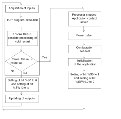
Illustration
The diagram below describes how a cold restart operates.

Operation
The table below describes the program execution restart phases on cold restart.
Phase |
Description |
|---|---|
1 |
The startup is performed in RUN
or in STOP depending on the status of the Program execution is resumed at the start of the cycle. |
2 |
The system carries out the following:
|
3 |
For this first restart cycle the system does the following:
|
Processing a Cold Start by Program
It is advisable to test the bit %SW10.0 to detect a cold start and start processing specific to this cold start.
Automatic
start in RUN has been selected. If this is not the case,
the PLC starts in STOP, the bit %S0 then switches to 1 on the first
cycle after restart but is not visible to the program because it is
not executed.Output Changes, for Premium and Atrium
As soon as a power outage is detected, the outputs are set in the fallback position:
either they are assigned the fallback value, or
the current value is maintained
depending on the choice made in the configuration.
After power restore, the outputs remain at zero until they are updated by the task.
Output Changes, for Quantum
As soon as a power outage is detected,
the local outputs are set to zero
the outputs of the remote or distributed extension racks are set in the fallback position
After power is restored, the outputs remain at zero until they are updated by the task.
With Modsoft/NxT/Concept, you cannot force outputs if the Quantum processor memory protection switch is set to "On".
With Control Expert, you can force outputs if the Quantum processor memory protection switch is set to "On".
With Modsoft/NxT/Concept, forced outputs retain their status after a cold start.
With Control Expert, forced outputs lose their status after a cold start.
| CAUTION | |
|---|---|
For Quantum 140 CPU 31••/41••/51••
These processors have a Flash EPROM memory of 1,435 KB which can be used to save the program and the initial values of variables.
When power is restored, you can choose the desired operating mode using the PLC MEM switch on the processor front panel. For detailed information on how this switch works, you can consult the Quantum manual.
off position: The application contained in this zone is automatically transferred to internal RAM when the PLC processor is powered up: cold restart of the application.
on position: The application contained in this zone is not transferred to internal RAM: warm restart of the application.


