

Time Stamping Function Blocks
2 function blocks are used for time stamping application:
GET_TS_EVT_M
GET_TS_EVT_Q
Each GET_TS_EVT_X function block fills a ring buffer in the PLC with the event time stamp entries from the time stamping source modules. This buffer is emptied when reading with the user application.
INT.Starting the Function Block
GET_TS_EVT_X instance is started when it is called in the user application.
The execution of the function block instance is evaluated at each call in the application.
Values of the function block parameters must not be changed between 2 calls of the same instance. The EFB execution must be completed successfully before modifying parameters.
Stopping the Function Block
The completion of the current operation performed by GET_TS_EVT_X function block is reached when:
Maximum number of events is reached in the buffer.
Buffer is full for the BMX ERT 1604 T module and BMX CRA 312 10 with buffer mode configured to stop the recording on buffer full.
An error is detected.
Once GET_TS_EVT_X EFB execution is finished,ACTIVE parameter is
set to 0.
Operating Mode of Enable, Active, Done and Error Parameters
The ENABLE, ACTIVE, DONE (or SUCCESS) and ERROR parameters operate as follows:
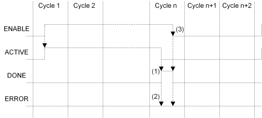
(1) DONE = 1 if no error, DONE = 0 if error
(2) ERROR = 0 if no error, ERROR = 1 if error
(3) If the ENABLE bit is reset to 0 before
completion, the function block is stopped (active bit to 0). To have
a complete block execution, the value of 1 must be applied on the
ENABLE bit until the operation has finished or until an error has
occurred.
The ENABLE parameter is written by the application.
The ACTIVE, DONE and ERROR parameters are read by the application.
To launch
the communication function only once, the ENABLE signal needs to be reset to 0 once the ACTIVE parameter
is set to 0. If the ENABLE parameter is maintained
to 1 once the ACTIVE parameter is set to 0, the communication
function is launched again and the ACTIVE parameter
will be set to 1 on the next cycle.
Reading the events in the
time stamping sources (BMX ERT 1604 T and BMX CRA 312
10 modules) may require several PLC cycles. Each function block
is controlled with the ENABLE parameter.
Rules to follow when setting the ENABLE parameter value:
When GET_TS_EVT_X function block is not active, all input parameters must be initialized before setting
ENABLEto 1, and not be changed during the function block activity.If
ENABLEparameter is maintained to 1 after the execution of the function block, GET_TS_EVT_X function block continues to fill the buffer using current value ofBEGINandENDindexes.If
ENABLEparameter is set to 0 before the GET_TS_EVT_X function block execution is completed successfully (ACTIVE= 0), the function block is stopped.
GET_TS_EVT_X Buffer and CTRLSTAMP Parameter Description
CTRL_STAMP DDT structure example and link
with the PLC buffer:
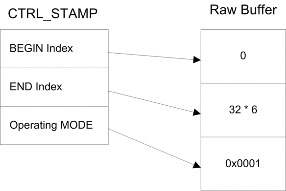
The example above shows the CTRL_STAMP content
after writing 32 events (1 event entry is 6 words long) in the PLC
buffer configured as follows:
PLC buffer is located and there are 32 events to write
Stop the recording when the buffer is full and continue with the previous value on power on.
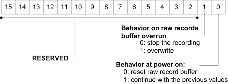
Operating MODE word structure:
Buffer level:
If BEGIN Index = END Index then the buffer is empty
If END Index + 6 = BEGIN Index then the buffer is full (in the preceding equation, 6 represents the size of 1 event). The buffer is full when there is one space left for 1 event (6 x
INT).
EFB behavior on buffer full depends on the Operating
MODE parameter, bit 1 value:
If Behavior on raw records buffer overrun is set to 0 (stop the recording), the buffer is not filled with new data.
If Behavior on raw records buffer overrun is set to 1 (overwrite buffer), elder data or overwritten with newer data. In this case, the EFB updates both BEGIN Index and END Index.
Communicating with Remote Ethernet Drops
When a communication function is used to perform communication exchanges with Ethernet drops, it is highly advisable to test the communication health status of the Ethernet drop before launching the communication function.
A communication function addressed to a non responding drop may take up to 2 minutes to complete, ending with an error status due to the transaction timeout delay (the remote participant has not answered within the timeout delay).
Communication health status is checked by one of those 2 information:
%SW172 to %SW173. Ethernet RIO drop detected communication error status. A bit in those status words is set to 0 when the corresponding connection between the PLC and the drop is not operating properly.
or DROP_COM_HEALTH. Field in the DDT structure associated with a drop.
Building the Application
When building an application with time stamping function, the following checks are performed by Control Expert:
Time stamped alias have to be linked to time stamped variables otherwise a detected error message is raised.
A time stamped variable has to be located on a time stamping source module or on a discrete module located in a drop with a BMX CRA 312 10 otherwise a detected error message is raised.
Device DDT with time stamped variables are correctly managed otherwise a detected error message is raised.
If the system includes a BMX CRA 312 10 module in an Ethernet I/O drop, an NTP server address must be configured.
Maximum amount of time stamped variables per drop with a BMX CRA 312 10 module is not exceeded.
Maximum amount of time stamped variables for the whole system is not exceeded.
Maximum amount of BMX ERT 1604 T modules for the whole system is not exceeded.
Components versions are compatible with time stamping function.
If channels are set to assume time stamping in a BMX ERT 1604 T module, a clock must be connected to the module. If no clock signal is detected, a detected error message is raised.
polling period should be lower than 20 seconds otherwise a message is raised at build time.
Dynamic arrays must be enabled otherwise a detected error message is raised.