|
|
Original instructions
|

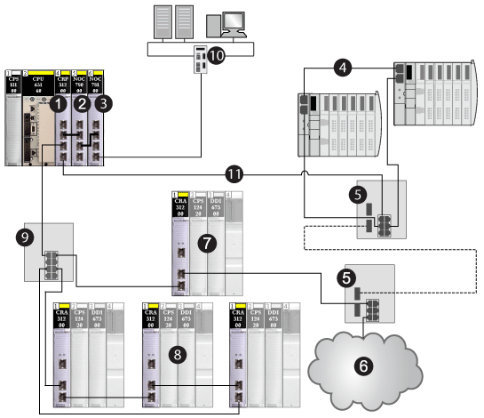
1140CRP31200 remote I/O head module on the local rack
2140NOC78000 distributed I/O head module (interlinked with a 140CRP31200 module to manage the distributed I/O sub-ring)
3140NOC78100 control head module that provides Ethernet transparency between the control network and the device network (combined remote I/O and distributed I/O devices)
4distributed I/O sub-ring
5DRSs configured to support copper-to-fiber transition on the main ring (connecting a distributed I/O sub-ring [4] and a distributed I/O cloud [6])
6distributed I/O cloud
7Ethernet remote I/O drop (which includes a •••CRA31200 adapter module) on the main ring
8Ethernet remote I/O drops (which include •••CRA31200 adapter modules) on a remote I/O sub-ring
9DRS (connected to a remote I/O sub-ring)
10control network (connected to the 140NOC78100 module on the local rack)
11main ring
|
The maximum number of...
|
...is...
|
|---|---|
|
hops in a network path
|
32
|
|
remote I/O devices
|
31
|
|
remote I/O devices in the main ring
|
15
|
|
devices in any sub-ring
|
16
|
|
distributed I/O devices on the network
|
128
|