In the following examples, the defined architectures restrict the number of hops a packet takes from a remote I/O drop to the . By restricting the number of hops, the application response time () for the system can be calculated.
In any Quantum EIO network topology, the hop count is used as a factor in
calculating network delay. To determine the hop count from the perspective of a remote I/O drop, count the number of switches (including embedded switches in remote I/O adapter and head modules) from the remote drop to the PLC.
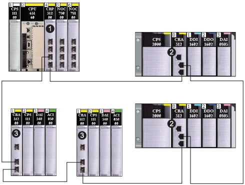
The following is an example of a simple daisy chain loop topology:
1
local rack with 140CRP31200 remote I/O head module
2
Modicon X80 remote I/O drop, each with a BMXCRA312•0 remote I/O adapter module
3
Quantum remote I/O drop, each with a 140CRA31200 remote I/O adapter module
In this simple daisy-chain loop Quantum EIO network topology — which consist of only the local rack and remote I/O drops — the following restrictions apply:
In this design, the network blocking port (of the embedded switch in each remote I/O adapter module) defaults to the port with the longer path to the PLC.
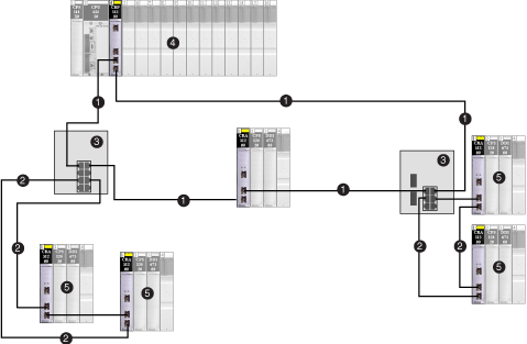
The following is an example of a high capacity system, consisting of a main ring, with multiple sub-rings:
1
main ring
2
remote I/O sub-rings
3
DRSs connecting the main ring to the sub-rings
4
local rack with remote I/O head module
5
remote I/O drops, each with a remote I/O adapter module
In this more complex Quantum EIO network topology — which consists of a single main ring, plus multiple sub-rings — the following restrictions apply:
|
The maximum number of...
|
...is...
|
|
hops in a network path
|
32
|
|
remote I/O devices
|
31
|
|
remote I/O devices in the main ring
|
15
|
|
devices in any sub-ring
|
16
|

