|
Configuring the Rapid Spanning Tree Protocol
|
|
|
Original instructions
|


|
Step
|
Description
|
|---|---|
|
1
|
Select the Services node in the navigation tree located on the left side of the Device Editor.
Result:The Services page opens.
|
|
2
|
In the Services page, set the RSTP field to Enabled, then click OK or Apply.
Result: The RSTP node appears in the navigation tree.
|
|
3
|
Select the RSTP node in the navigation tree, then click on either the General or Advanced tab to display that page.
|
|
Property
|
Description
|
|---|---|
|
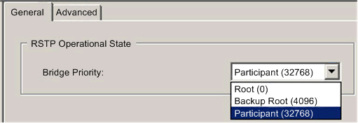
RSTP Operational State: Bridge Priority
|
Select one of the following values in the drop-down list:
NOTE: Network switches running RSTP software periodically exchange information about themselves using special packets called Bridge Protocol Data Units (BPDUs), which act as a heartbeat. The Bridge Priority value is contained in the BPDU and establishes the relative position of the switch in the RSTP hierarchy. |
|
Property
|
Description
|
|---|---|
|
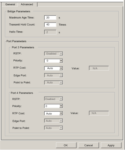
Bridge Parameters:
|
|
|
Maximum Age Time
|
This value is set to The length of time, from 6 to 40 seconds, that the switch waits for receipt of the next hello message, before initiating a change to the RSTP topology. Default = 40 s.
|
|
Transmit Hold Count
|
The maximum number of BPDUs, from 1 to 40, that the switch can transmit per second. Default = 40.
|
|
Hello Time
|
(read-only) The frequency—set at 2 seconds—that the embedded switch sends heartbeat BPDUs.
|
|
Port Parameters (These properties can be separately configured for ports 3 and 4):
|
|
|
RSTP
|
(read-only) This property is set to Enabled in the Services page.
|
|
Priority
|
The priority assigned to the switch port, an integer from 0 to 240 in increments of 16. Default = 0. This value is used by the RSTP process if it needs to break a tie between two ports on the same switch when identifying a:
|
|
Path Cost
|
The method used to determine the path cost through the embedded switch. Values include:
|
|
Edge Port
|
(read-only) Set to a fixed value of Auto. The RSTP process automatically determines if the port is an RSTP edge port.
|
|
Point to Point
|
(read-only) Set to a fixed value of Auto. The RSTP process automatically determines if the port is an RSTP point-to-point port.
|