|
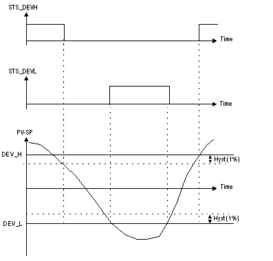
Alarm on Deviation
|
|
|
(Original Document)
|

|
Parameter
|
Symbol
|
Type
|
Thresholds
|
Default Value
|
R/W
|
|---|---|---|---|---|---|
|
Process Value
|
PV
|
REAL
|
-3.4E38 / 3.4E38
|
/
|
R
|
|
Setpoint Value
|
SP
|
REAL
|
-3.4E38 / 3.4E38
|
/
|
R
|
|
Parameter
|
Symbol
|
Type
|
Thresholds
|
Default Value
|
R/W
|
|---|---|---|---|---|---|
|
High deviation threshold
|
DEV_H
|
REAL
|
0.0 / 3.4E38
|
5.0
|
R/W
|
|
Low deviation threshold
|
DEV_L
|
REAL
|
-3.4E38 / 0.0
|
-5.0
|
R/W
|
|
Parameter
|
Symbol
|
Type
|
Thresholds
|
Default Value
|
R/W
|
|---|---|---|---|---|---|
|
Upper Limit
|
STS_DEVH
|
EBOOL
|
/
|
/
|
R
|
|
Lower Limit
|
STS_DEVL
|
EBOOL
|
/
|
/
|
R
|
|
Or alarms (*)
|
STS_ALARMS
|
EBOOL
|
/
|
/
|
R
|