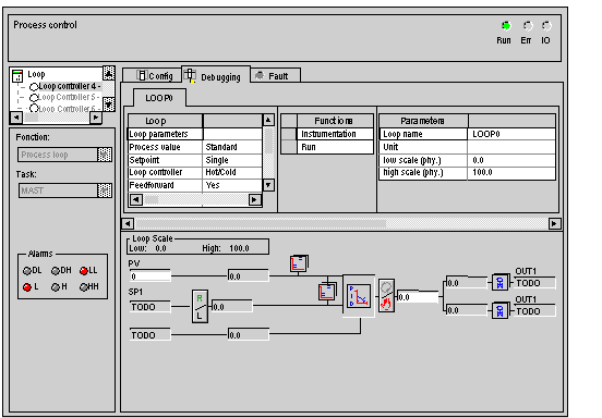
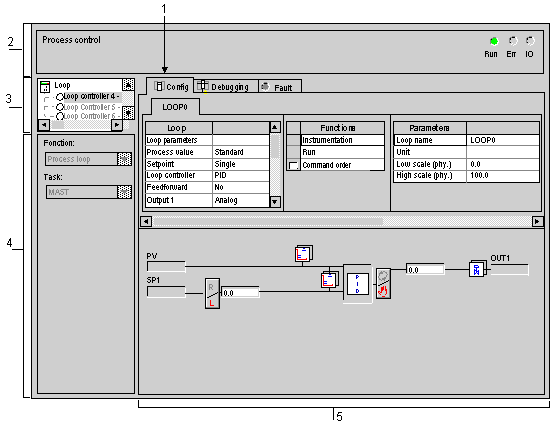
Description of Loop Controller Configuration Screens
(Original Document)
At a Glance
There are two different types of loop control configuration screens:
Illustration
The following figure shows a configuration screen.
Description
The following table lists all components of the configuration screen, as well as their respective functions.
Address
Component
Function
1
Tabs
The foremost tab indicates the current mode (in this instance: Configuration). Select each mode by clicking on the corresponding tab. The following modes are available:
  • Configuration,
  • Debugging, accessible only in Online mode,
  • Diagnostics, (Default) accessible only in Online mode.
2
Module area
Displays the abridged module indicator.
There are three indicators in the same zone that provide the status of the PLC in online:
  • RUN indicates the status of the PLC,
  • ERR indicates a fault on the processor or embedded devices.
  • I/O indicates a fault from a module, channel or configuration.
3
Channel area
Is used:
  • By clicking on the reference number, to display the tabs:
    • Description which gives the characteristics of the device.
    • I/O Objects which is used to presymbolize the input/output objects.
    • Fault which shows the device faults (in online mode).
  • To choose the loop controller
  • To display the Symbol, the name of the channel defined by the user (using the variable editor).
4
Global Parameters area
Use this area to select the global parameters associated with to the channel:
  • Function: Functions associated with the channel and available are the following:
    • a process loop,
    • a cascade loop,
    • an auto selector loop,
    • three single loops,
    • a setpoint programmer.
  • Task: defines the MAST or FAST task through which the channel's implicit exchange objects will be exchanged. This parameter is invariable.
5
Configuration area
Use this area to set configuration parameters applicable to the channel. Some options may be grayed-out to indicate that they are not available.
This area comprises two sections:
  • the function selection area,
  • the visualization and configuration area for the loop controller block diagram.
Illustration
The figure below represents a debug screen.
Utilities Accessible through the Debugging Screen
The following utilities are accessible through the debugging screen: