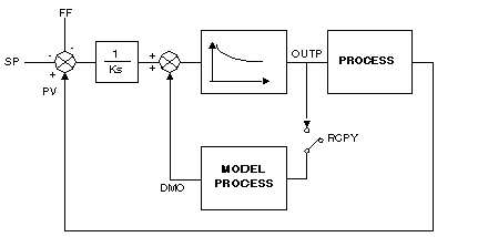
The model loop controller is used where there are significant pure delays in relation to the time constant of the process, a case which cannot be processed satisfactorily by classic PID process control. The model loop controller is also useful for regulating a non-linear process.
The model is first order + delay. Nevertheless, this loop controller can process any stable or aperiodic process, whatever its order. The parameters to be given are:
-
The static gain (delta process value/delta command ratio in open loop).
-
The equivalent time constant (response time/3).
-
The process pure delay value (estimated value).
-
The time constant in open loop/time constant in closed loop ratio.
The diagram of principal of the model loop controller algorithm is as follows:
Installing the Loop Controller
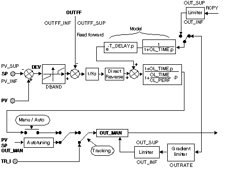
Installing the model loop controller is similar to installing a PID loop controller. The adjustment of PID parameters KP, TI and TD being replaced by gain adjustment, the time constant, the pure delay of the process model and the ratio of the time constants in open and closed loop.
The model loop controller has the same inputs and outputs as a PID (PV, RSP, FF, OUTP). It also has the RCPY optional input (model external input) which can be used to input the processís real input (the flow measured on output from a valve, for example).
NOTE: The DMO model output is not directly comparable to the PV process value. At this level, the model does not take into account Ks static gain and possible compensation (BIAS).
The functions other than the command calculation are identical to those of the PID:
-
Direct or inverse action.
-
Feed forward action to compensate for disruptions.
-
Dead band on deviation.
-
High and low limit of the output signal.
-
Limit of the output gradient.
-
Selecting Automatic / Manual operating mode.
-
Tracking Mode.
-
Autotuning of the main coefficients.
In the processs used by this loop controller, the delay is either:
These two cases are processed using a register (buffer) of size which can be parameterized. According to the size of this register, it will be possible to sample either all the sampling periods, one period in two, or one period in three etc.
It is possible to increase or decrease the delay T_DELAY during the execution of the program. The new delay is applied instantly, as long as it is compatible with the size of the register. The sampling period of the delay remains unchanged.
If the value of T_DELAY becomes too large compared to the size of the register it becomes impossible to store enough input values to reach the required delay, if the sampling is done in the same period. Therefore, the sampling period of the delay is recalculated and the output is only valid after a time equal to the new delay. To avoid this problem, you are advised to set the size of the register, taking into account the possible increases in the delay T_DELAY.
If the delay decreases by default the sampling does not change. All the same, it is possible to order a new sampling calculation if necessary.
In the case of a dynamic modification of the task time or the sampling period, the output is only valid after a time equal to the delay.
All dynamic modifications of T_DELAY between 0 s and 30 s is taken into account immediately without changing the sampling of the register.
Example
|
Sampling period
|
T_ECH = 300 ms
|
|
Size of delay register
|
50
|
|
Delay
|
T_DELAY = 25 s
|
|
Therefore, the delay register is sampled every 2 T_ECH
|
50 x 2 x 0,3 = 30 s > 25 s
|
The function diagram of the model loop controller is as follows:

