Device DDT Instance
When adding a module to a rack, Control Expert software instantiates the associated device DDT structure. The main family of modules concerned by device DDT is the I/O modules family, some specific modules are also concerned. The device DDT name syntax is explained in the section on Device DDT Naming Rule.
Each module is associated with one implicit device DDT instance.
Implicit Device DDT instances are created by default on device insertion and refreshed automatically by the PLC. They contain the modules status, modules and channels health bits, values of the modules inputs, values of the modules outputs, etc.
Renaming a Device DDT
The following table describes a way to rename a module device DDT:
Step |
Action |
|---|---|
1 |
In the , double-click the module that contains the device DDT to rename. |
2 |
In the module window, select the tab. |
3 |
Select the module (not the channel). |
4 |
Modify the device DDT name. NOTE: The total name length is limited to 32 characters.
NOTE: A name needs to be unique in an application.
|
5 |
Validate the name changes in the advice window. This advice window appears when selecting another tab or view. |
| WARNING | |
|---|---|
Copying and Pasting a Module
During a module copy/paste action, the pasted module respects the default naming rule linked to its topological location.
Moving a Module
Moving a module does not modify its name.
If the same module type is inserted in the slot freed by the module shifting, the new inserted module should get the same topological name. In order to keep the naming uniqueness, _rrrrrr is added at the end of the string (rrrrrr being a random character series).
Replacing a Hot Standby CPU
Replacing a Hot Standby CPU does not modify the device DDT name of the CPU.
Checking the Device DDT Owner
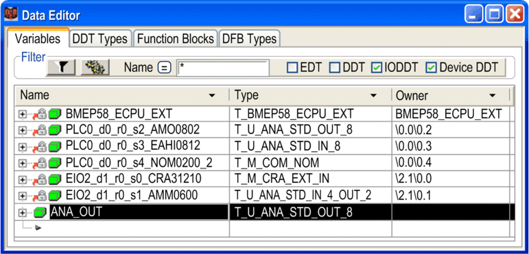
When a module is moved or a Device DDT is renamed, it may be difficult to locate the module in the architecture. This information is provided in the column of the . Displayed columns are configured as needed.
Creating a Device DDT Instance
Perform the following steps to create a Device DDT instance:
Step |
Action |
|---|---|
1 |
Select the tab in the data editor. |
2 |
Double-click the empty cell (marked with an arrow) and enter the name of the instance. |
3 |
Double-click the corresponding field and click the following
button:
 Results: The dialog appears. |
4 |
In the area, display the index. Where x.y indicates the Control Expert software version. |
5 |
Select the family ( for example) and the corresponding Device DDT type. |
6 |
Confirm with . |
Example: Instance ANA_OUT of type T_U_ANA_STD_OUT_8:

Linking a Device DDT Instance to a Module
Use the following procedure:
Step |
Action |
|---|---|
1 |
Create a Device DDT as explained previously. |
2 |
In the , double-click the module to be associated to the created device DDT. NOTE: The
created device DDT can only be linked to a module of the same type.
For example, an 8 analog input module can only be linked to an 8 analog
input device DDT.
|
3 |
In the module window, select the tab. |
4 |
Select the module (not the channel). |
5 |
In the list, select the name of the device DDT created (instead of the current name). |
6 |
Validate the name changes in the advice window. This advice window appears when selecting another tab or view. NOTE: Once a module is linked to a new device
DDT, the variables that were linked to former device DDT name do not
address the module anymore.
|
7 |
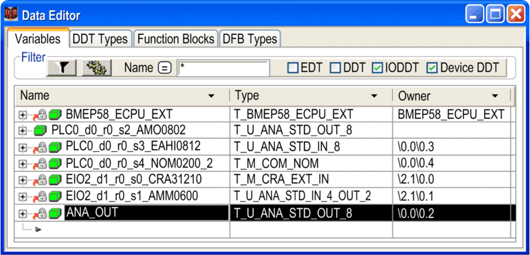
The previously created Device DDT instance is now linked to the module. It is displayed as follows in the data editor:  |
 in front of its name in
the data editor.

