Overview
The tab is only available for the Modicon M340 hardware platform equipped with a State RAM memory area.
It allows defining the type of memory management for the selected input / output module.
The option you select here must comply with the type of memory management you selected for the processor.
The following settings are possible:
If... |
Then... |
|---|---|
memory management is configured for the processor |
you can only select memory management for the discrete and analog modules. |
memory management is configured for the processor |
you can select either or memory management for the discrete and analog modules. |
The memory management settings of the modules are compared with the memory management settings of the processor during . If any inconsistencies are detected, an appropriate message is displayed in the output window.
The type of memory management you selected for the processor will be used as default setting for the parameter in the tab.
Any application made with Control Expert is automatically configured with address configuration for topological addressing as the default setting.
If you want to import a legacy LL984 Compact application which uses Modbus request to communicate with an HMI, you have to use State RAM addressing to preserve the Modbus exchange between PLC and HMI.
Specific Configuration Dialogs in Case of LL984 Import
If an ST section has been created during import to emulate Compact configuration behavior, the converter creates a specific I/O module configuration with specific configuration dialogs.
The area is grayed and the choice is fixed to .
In the area and are defined by the converter.
You can only delete these modules. Copy and paste of these modules is not possible.
Memory Management
The area of the tab provides the following options:
Option |
Description |
|---|---|
|
Select this option to work with pure topological addressing. If this mode is selected, the parameters in the area of this dialog box are disabled. |
|
Select this option to work with State RAM addressing for IO access. Topological addressing remains possible for some IO objects (%CH, %I.ERR, ...) but it’s not possible to access IO values (%I, %Q). With this option selected, define further State RAM options in the area of this tab for the different types of modules. NOTE: With this type of memory management,
all channels are associated with only one task (MAST or FAST).
|
I/O Objects
Memory
Debug
Fault
State RAM Configuration for Discrete Modules
Depending on the selected module, the area of the tab contains parameters for discrete input modules, discrete output modules or for discrete mixed modules. They are available if the option is selected in the area.
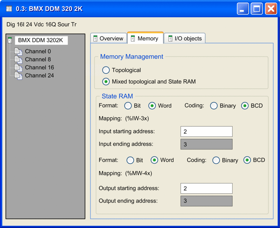
The figure below shows the tab for a discrete mixed input / output module as an example:

The area contains the following parameters:
Parameter |
Description |
|---|---|
|
|
|
This parameter is only available for channel mapping in word mode, that is if the parameter is set to .
|
|
This parameter allows you to define the es for the inputs and outputs. The following sizes of the memory areas are possible:
NOTE: The State RAM address starts at address 0,
but the first available address for discrete and analog modules is
%I1, %M1, %IW1, and %MW1. |
(1) When Word is selected as the Format, the LSB of the Word is mapped to:
Input 0 on discrete input modules
Output 0 on discrete output modules
State RAM Configuration for Analog Modules
Depending on the selected module, the area of the tab contains parameters for analog input modules, analog output modules or for analog mixed modules. They are available if the option is selected in the area.
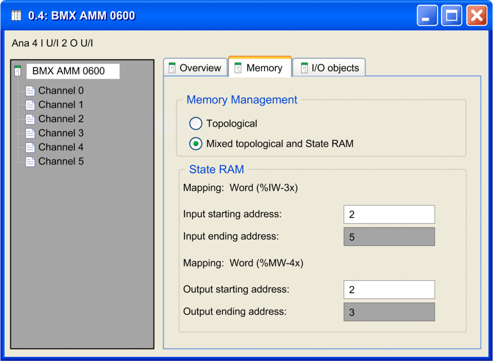
The figure below shows the tab for a mixed analog input / output module as an example:

The area contains the following parameters:
Parameter |
Description |
|---|---|
|
This parameter allows you to define the es for the inputs and outputs. The following sizes of the memory areas are possible:
|


