Access to the Configuration Screen
Proceed with the following steps:
Step |
Action |
|---|---|
1 |
Select the processor. Example: 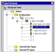 |
2 |
Using the contextual menu, click Open. |
3 |
Select the Configuration tab. |
Memory Management
The configuration screen differs, depending on the type of memory management to be used.
The option you select here must comply with the type of memory management you select for the input and output modules.
The following settings are possible:
If... |
Then... |
|---|---|
memory management is configured for the processor |
you can only select memory management for the discrete and analog modules. |
memory management is configured for the processor |
you can select either or memory management for the discrete and analog modules. |
The memory management settings of the processor are compared with the memory management settings of the modules during . If any inconsistencies are detected, a appropriate message is displayed in the output window.
The type of memory management you selected for the processor is used as default setting for the parameter in the tab for input / output configuration.
If you want to import a legacy LL984 Compact application which uses Modbus request to communicate with an HMI, you have to use State RAM addressing to preserve the Modbus exchange between PLC and HMI.
Configuration of the Processor
Configuration screen for topological memory management:
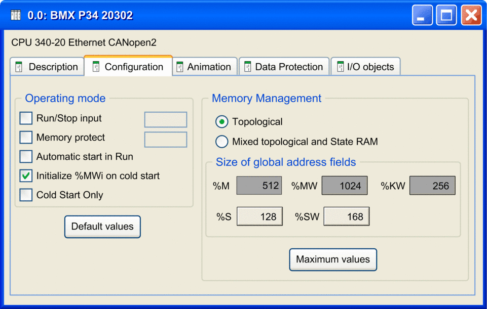
| CAUTION | |
|---|---|
Proceed with the following steps:
Step |
Action |
|---|---|
1 |
If you wish, enable the option. Do not enable this option if the associated discrete input is mapped in State RAM because this inhibits the PLC start-up. |
2 |
If you wish, enable the option. The protection is activated by an input bit. The protection level depends on the Firmware versions, see detailed information. |
3 |
If you wish, enable the option. |
4 |
Confirm whether the internal words %MWi are to be initialized on cold start triggered
by software (application download, initialize command, restore command, |
5 |
If you wish, enable the option. |
6 |
Define the type of :
|
7 |
Proceed with address configuration for the 2 different addressing types as described in the following separate descriptions. |
%I1, %M1, %IW1, and %MW1.Topological Addressing
Proceed with address configuration for topological addressing as follows:
Step |
Action |
|---|---|
1 |
In the of the dialog
box define for the application the
number of internal bits |
2 |
Define the number of internal words |
3 |
Define the number of constants |
The system bits and system words are fixed by the manufacturer.
M340 applications of version 6.0 and earlier are automatically configured with this address configuration for topological addressing.
Mixed Topological and State RAM Addressing
Configuration screen for mixed topological and State RAM memory management:
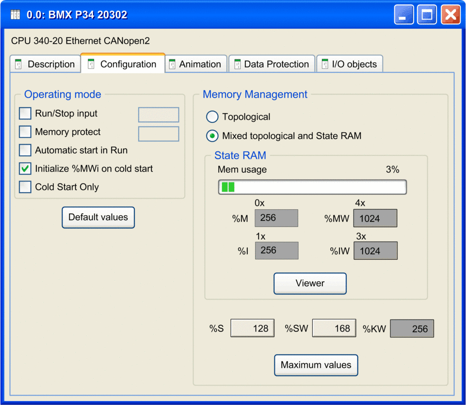
For mixed topological and State RAM addressing, the following options are additionally available in the configuration screen:
Option |
Value |
Description |
|---|---|---|
|
The value (expressed as a percentage and displayed on the scale bar) depends on the memory usage of the Modicon M340 configuration. |
A bar graph displays the percentage of the memory already in use. |
|
Enter the appropriate values. The values depend on the configuration. |
Size of the different memory areas. NOTE: The values for and have to be divisible by 8.
|
|
||
|
||
|
||
|
– |
Opens the State RAM Viewer tab which displays the allocation of used memory. |
%I1, %M1, %IW1, and %MW1.Pre-set values
To select the:
default values, press the Default values button,
maximum values, press the Maximum values button,
Window displayed by pressing the Default values button:
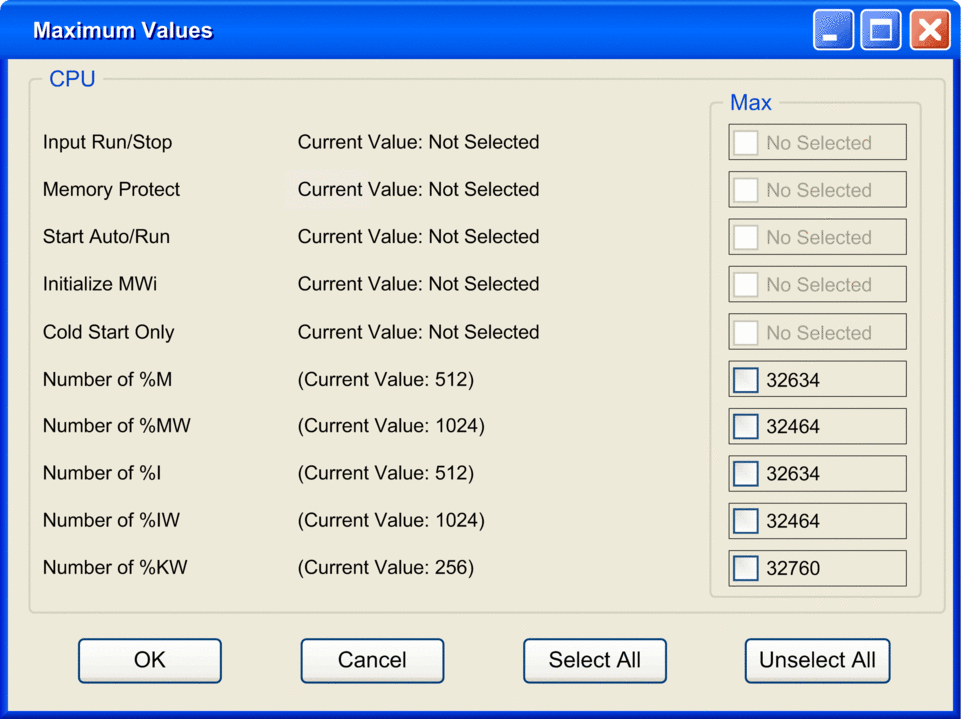
Use of the command buttons:
Button |
Role |
|---|---|
Unselect All |
Is used to invalidate all the default values posted on the right of the check boxes if they have been selected. |
Select All |
Is used to select all the default values posted on the right of the check boxes. |
Cancel |
Is used to exit. |
OK |
Is used to exit taking the values into account. |
Input RUN/STOP
The input %Ir.m.c can be parameterized to switch the PLC to RUN/STOP mode in the following way:
%Ir.m.cto 1 -> the PLC switches to RUN (execution of the program),%Ir.m.cto 0 -> the PLC switches to STOP mode (stop program execution).
%Ir.m.c input.An error on the RUN/STOP input causes a switch to STOP.
Do not enable this option if the associated discrete input is mapped in State RAM because this inhibits the start-up of the PLC.
Memory protect
The input %Ir.m.c can be parameterized to protect the internal application ram and the memory card in the following way:
%Ir.m.cto 0 -> the internal application and the memory card are not protected,%Ir.m.cto 1 -> the internal application and the memory card are protected.
For Firmware versions < 2.60, the Memory Protect function prohibits the transfer of a project into the PLC and modifications in online mode, but RUN/STOP commands are available.
For Firmware versions greater and equal to 2.60, the Memory Protect function prohibits the transfer of a project into the PLC and modifications in online mode, for cybersecurity improvement, the connection to the PLC is forbidden then the RUN/STOP command are not available.
Automatic start in Run
The enabling of this option automatically changes the PLC to RUN mode at the time of a cold start.
Initialize %MWi
On a cold start or on download if you check the box (default state):
the
%MWiare handled like other global variables (initialized to 0 or initial value, according to current application) in all cold start cases,
On cold start or on download if you uncheck the box:
if
%MWwere previously saved in internal flash memory (using the%SW96word) they are restored from internal flash memory,if not,
if cold start is linked to a power-off or of a push on the reset button, the
%MWare initialized:if not, the current values of
%MWare maintained.
%MW than the previous one, the added %MW are set to 0 (non-zero initial values are not applied).Cold Start Only
If checked, this option forces the cold start of the application, instead of the normal warm start.
By default, the Cold Start Only option is unchecked.
The Cold Start Only option is only supported for CPU with OS version V2.1 or later.
An application using this functionality is not:
downloadable on a PLC with a previous version,
executable on a PLC with a previous version,
usable with Unity Pro V4.0 or earlier.
Unity Pro is the former name of Control Expert for version 13.1 or earlier.
Memory Management
This area of the dialog box allows you to define the type of addressing (topological or mixed addressing).
For mixed addressing it contains a bar graph indicating the size of the memory used in your project in relation to the maximum memory size and a button opening the State RAM memory viewer.
State RAM Memory Viewer
The following screen displays the content of the State RAM memory areas of the M340 processor:
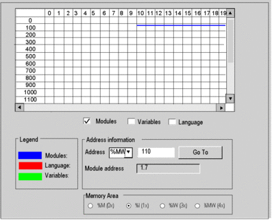
Description of the screen zones
Zone |
Description |
|---|---|
Table |
This table represents the mapping of the memory area selected with the Memory Area selection buttons. The occupied memory addresses are marked by dashes:
The scroll bars can be used to access the entire memory area. |
Modules, Variables and Language checkboxes |
These checkboxes are used to filter the information displayed in the table. If, for example, is the only checkbox that is selected, only module-type information is displayed. |
Address information |
By entering the object and its address in the Address fields and clicking on the Go To button, you display directly the address in the table (without using the scroll bars). This zone also has a display function; it displays the object and address of the box selected in the table. For module-type objects, it also gives the topological address of the module concerned. |
Memory Area selection buttons |
These buttons are used to select the memory area to display in the table:
|
Size of Located Data in Case of State RAM
The following table shows maximum and default size of located data in case of State RAM configuration according to the type of processor.
Type of Objects |
Address |
BMX P34 1000 Processor |
BMX P34 2000, 20102, 2020, 20302 Processors |
||
|---|---|---|---|---|---|
Maximum Size |
Default Size |
Maximum Size |
Default Size |
||
output bits and internal bits |
|
32765 |
752 |
65530 |
1504 |
input bits and internal bits |
|
32765 |
752 |
65530 |
1504 |
input words and internal words |
|
32765 |
256 |
65530 |
512 |
output words and internal words |
|
32765 |
256 |
65530 |
512 |
Impact of a Cold Start on %I and %IW Areas
After a Cold
Start or %S0 setting, the %I and %IW areas are set to 0 and forcing state is reset.
CPU Modbus Server Uses %I and %IW Areas
When the State RAM is configured in a CPU, the Modbus server access to
%Iarea for all input bits operations and to%IWarea for all input words operations.Base address
%SW138and%SW140are not used in this case.The first object address in a Modbus request (0000) corresponds to
%I1or%IW1.With Modicon M340 using firmware V2.4 or later, when the State RAM is not configured, the Modbus server behaves as in firmware V2.3.
Base address for %M and %MW in system words %SW139 and %SW141 are used whether State RAM is configured or not.
Protecting Located Data
Before any action on the data memory protection, you must activate this feature in your project settings.
In the Control Expert main window, click . Then select the Data memory protect box and click Apply.
The data memory protection feature is supported by M340 CPU with the firmware V3.30 or later. For details, refer to chapter Data Memory Protection.
Follow the procedure below to define the located data to protect:
Step |
Action |
|
|---|---|---|
1 |
In the Control Expert , double-click to display the main rack. Then double-click on the M580 CPU (but not on the Ethernet connectors) to view its properties. |
|
2 |
Select the tab: 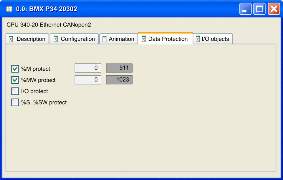 |
|
3 |
Select the boxes to enable the data protection: |
|
|
The protected area is always located at the end of the %M area. Only the starting address of the protected area can be set. The end address of the protected area is not configurable (grayed). The end address of the protected area equals to n-1 where n is the number of available %M defined by the PLC abilities and set in the tab. If is selected, you can enter the starting address or the %M data to protect. By default, the starting address is 0. Unchecking the %M protection reset the starting address. |
|
|
The protected area is always located at the end of the %M area. Only the starting address of the protected area can be set. The end address of the protected area is not configurable (grayed). The end address of the protected area equals to n-1 where n is the number of available %MW defined by the PLC abilities and set in the tab. If is selected, you can enter the starting address or the %M data to protect. By default, the starting address is 0. Unchecking the %MW protection reset the starting address. NOTE: Array variables which are mapped on a %MW range
must be entirely inside or entirely outside of the protected %MW range.
|
|
|
If selected, all I/O objects (including DTM-objects) are protected. NOTE: except state Ram
objects.
|
|
|
If selected, all system bits and system words are protected. |
|
4 |
Select (or click the |
|


 toolbar button) to save
the configuration.