At a Glance
The DTM Browser is the main component of the Control Expert FDT Container. The DTM devices are managed from the browser.
DTM Browser
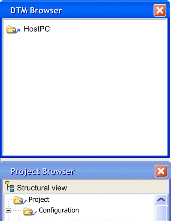
To open the DTM Browser use the Tools menu -> DTM Browser:

The root of the DTM Browser is HostPC, which is the PC platform for the Control Expert project.
DTM Browser DTM Types
The DTM Browser displays the configured DTMs added to the connectivity tree HostPC with hierarchical levels (nodes).
There are 3 types of DTMs:
Communication DTMs (drivers)
Any COM DTM can be plugged directly under the root node (HostPC) and must be at the 1st level
A COM DTM can support Gateway DTMs or Device DTMs as children if their protocols are compatible
Gateway DTMs
A Gateway DTM can support other Gateway DTMs or Device DTMs as children if their protocols are compatible.
Device DTMs
A Device DTM does not support any child DTMs
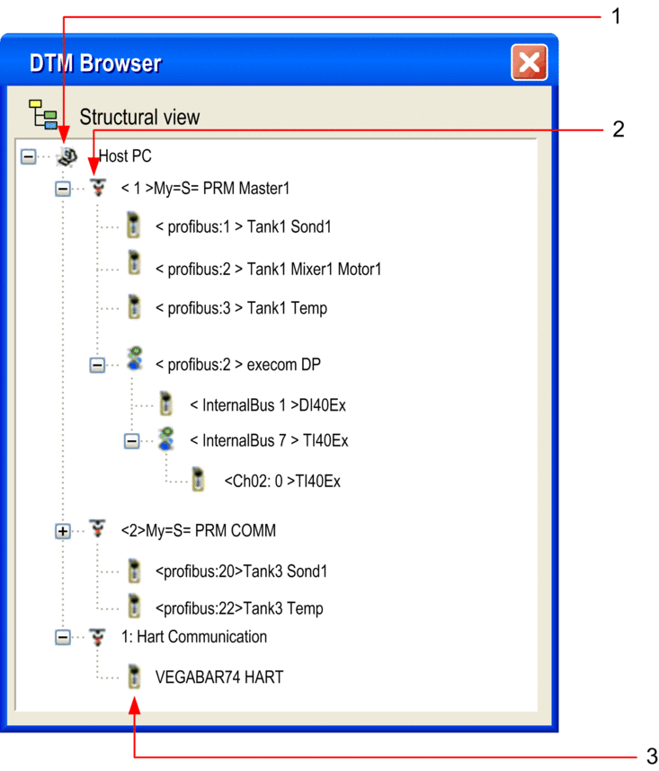
The following illustration is a connectivity tree:

The following table describes the different hierarchical nodes of the connected DTMs in the above example connectivity tree:
Number |
Description of Level |
|---|---|
1 |
The First Level is the root node, HostPC, which is where the PC is connected to the physical network. |
2 |
The Second Level devices are communication DTMs (drivers) that connect to their physical communication devices on the network. |
3 |
The Third Level devices are connected to a communication device. |
Copy Paste feature
Each device DTM configured can be copied and pasted to easily create configuration.
Operating mode to make a Copy/Paste:
Make a right click on the Device DTM you want to Copy/Paste
Select
Make a right click on the Communication DTM or Gateway DTM in which you want to paste the Device DTM
Select .
Tree View Naming
Each DTM has a default name when inserted into the browser. The syntax is the following: <Channel: Bus Address> User Name:
Channel
This is the name of the channel communication media where the DTM is plugged in. This name is read from the DTM and is set by the device vendor.
Bus Address of the device. It can be either:
The connection point on its parent gateway network
The slot number in the modular device parent internal bus
This information is supplied by the parent DTM and can be modified in Control Expert if the DTM supports this modification.
User Defined Name
This name is set by default to the vendors name for the DTM name (which is the default vendor name), but can be reset.
Examples:
For a communication DTM
<1> My =S= PRM COMM, where 1 is the references number.
For a Device or a Gateway
<Profibus:1> Tank1Sond1 means that the DTM is connected to the Profibus channel of its “parent” at connection point 1.
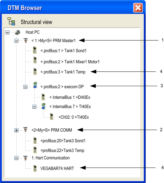
Example Connectivity Tree
The following illustration is a connectivity tree:

Number |
Node Level Description |
|---|---|
1 |
This Second Level PRM Comm Master communication DTM connects to the HostPC for communication with a PRM device via the Ethernet for DPV0 and DPV1 exchanges. |
2 |
This Second Level PRM Comm communication DTM connects to the HostPC for communication with a PRM device via the Ethernet for DPV1 exchanges. |
3 |
This Third Level Profibus Gateway DTM connects simple or Gateway devices to the higher communication DTM. |
4 |
The Simple or Compact DTMs are connected to communication DTMs that allow them to communicate with their physical devices on the network. These tree leaves do not allow any sub-connectively. |


