Overview
Our system time stamping mechanism can manage not only internal variables or inputs, but also events generated and time stamped by external devices (e.g. a breaker). Such events are also called user events in the following documentation.
When dealing with user events, user application must make the acquisition of these events, and push them into the internal buffer of the PLC. Then these external events will be processed and forwarded to SCADA as the other internal time stamped events.
Each cycle the system time stamping scans all the user events to detect a value change (transition). In case of detection, the event is stored in the event buffer of the CPU.
Declaring a User Event in Control Expert
To time stamp a user event:
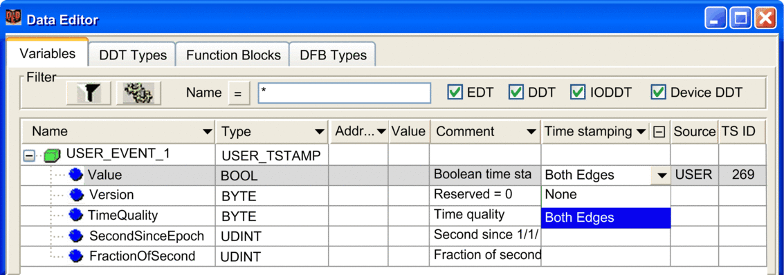
In the , instantiate for each user event a variable with type USER_TSTAMP (DDT).
NOTE: Use only non-located variables when creating a variable of the type USER_TSTAMP. Using a located variable will cause an error to be detected during operations and the process will not operate as intended.Set to the field of the data Value (default setting is ). This setting enables the variable for time stamping, with set as the source.
when an event is received, fill by programming the data structure of the user event variable, especially the Value (boolean) and the event occurrence time.

USER_TSTAMP DDT
Element |
Type |
Description |
|
|---|---|---|---|
Value |
BOOL |
User event value scanned by the system time stamping. |
|
Version |
BYTE |
Reserved = 0 |
|
TimeQuality |
BYTE |
Bit 7 = LeapsSecondsKnown. |
|
Bit 6 = ClockFailure |
|||
Bit 5 = ClockNotSynchronized. |
|||
Bit 4 to 0 = TimeAccuracy |
|||
00000 |
n = number of significant bits in FractionOfSecond Minimum time interval shall be 2(-n) s. For n = 10, the time accuracy is approximately 1 ms. |
||
... |
|||
01010 |
|||
11011 |
Time catch up |
||
11100 |
Value synchronization |
||
11101 |
I/O fault |
||
11110 |
Buffer full synchronization |
||
11111 |
Accuracy unspecified |
||
SecondSinceEpoch |
UDINT |
Number of seconds since midnight (00:00:00) 1970/01/01 (UTC time). |
|
FractionOfSecond |
UDINT |
This is the fraction of the current second when the value of the time stamped variable has been determined. It is the sum of the numerical values assigned to each bit for those bits which are set to 1:
NOTE: Bits 31 to 24 are not used
|
|
Time stamping Behavior on User Events
In normal operation conditions, the system time stamping, scans the USER_TSTAMP variables. When a rising or a falling edge on the variable is detected, the system time stamping stores the user event in the event buffer of the CPU.
The time information of each time stamped user event is the time and the quality read in the DDT.
The system time stamping solution also manages the report of user event values to the SCADA system even when the system is facing operating modes that differ from the normal operating conditions:
| Values Synchronization | This state allows a synchronization of the values for example after a SCADA reset. The system time stamping updates the event buffer of the CPU with the values of all the user event variables. The time is the time read in the DDT and TimeAccuracy bit are forced to 11100. |
| Buffer Full Synchronization | The system time stamping updates the event buffer of the CPU if the current value is different from the last value recorded.The time is the time read in the DDT and TimeAccuracy bits are forced to 11110. |
Limitations
The system time stamping does not check:
the consistency of the time read in the user event DDT.
NOTE: The time information must be compliant with the time format defined in IEC 61850-7-2 Edition 2.that the interval of time between two user events is greater than 1 ms. You have to respect SCADA limitation.
The system time stamping does not manage:
the time catch up on user events. You need to provide ascending time.
the following TimeQuality bits:
bit 7: LeapsSecondsKnown
bit 6: ClockFailure
bit 5: ClockNotSynchronized.
You need to manage these 3 bits.


