Presentation
Original instructions
Function
The 140 NOM 212 00 is a dual channel Network Option Modul (NOM), connected via a twisted pair Modbus Plus cable network
Illustration
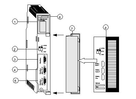
The following figure shows the parts of the Modbus Plus 140 NOM 212 00 modules.
1 
LED Area
2 
Comm Parameter Slide Switch
3 
Modbus Connector
4 
Modbus Plus Connector (Chan A)
5 
Modbus Plus Connector (Chan B)
6 
Model Number, Module Description, Color Code
7 
Removable door
8 
Customer Identification Label, (Fold label and place it inside door)
Front Panel Switches
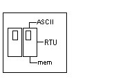
Two, three-position slide switches are located on the front of the unit. The switch on the left is not used. The three-position slide switch on the right is used to select the comm parameter settings for the Modbus (RS-232) port provided with the Modbus Plus option module. Three options are available, as shown below.
The following figure shows the front panel switches.
NOTE: If the left-hand switch is in the upper position and right-hand switch is set to mem then, as of firmware version 2.20, bridge mode is deactivated. This means that the network connection between Modbus and Modbus Plus is locked.
The NOM hardware defaults to bridge mode when the front panel switch is set to RTU or ASCII mode. When networking controllers, a panel device connected to the NOM Modbus port can communicate with the controller to which it is conected, as well as log into any nodes on the Modbus Plus network.
Rear Panel Switches
Two rotary switches are located on the rear panel of the modules. They are used together to set the Modbus Plus node and Modbus port address for the unit.
NOTE: The highest address that may be set with these switches is 64.
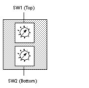
Rotary SW1 (top switch) sets the upper digit (tens), and rotary SW2 (bottom switch) sets the lower digit (ones) of the Modbus Plus node address. The illustration below shows the setting for an example address of 11.
SW1 and SW2 Switches Figure
The following figure shows the SW1 and SW2 switches.
NOTE: If "0," or an address greater than 64 is selected, the Modbus + LED will be "on" steady, to indicate the selection of an invalid address.
SW1 and SW2 Address Settings
The following table shows the address settings for the SW1 and SW2 switches.
Node Address
SW1
SW2
1 ... 9
0
1 ... 9
10 ... 19
1
0 ... 9
20 ... 29
2
0 ... 9
30 ... 39
3
0 ... 9
40 ... 49
4
0 ... 9
50 ... 59
5
0 ... 9
60 ... 64
6
1 ... 4
NOTE: If "0," or an address greater than 64 is selected, the Modbus + LED will be "on" steady, to indicate the selection of an invalid address.
ASCII Comm Port Parameters
The following table shows the fixed setting of the ASCII comm port parameters.
Baud
2,400
Parity
Even
Data Bits
7
Stop Bits
1
Device Address
Rear panel rotary switch setting
Setting the slide switch to the middle position assigns remote terminal unit (RTU) functionality to the port; the following comm parameters are set and cannot be changed:
RTU Comm Port Parameters
The following table shows the RTU comm port parameters.
Baud
9,600
Parity
Even
Data Bits
8
Stop Bits
1
Device Address
Rear panel rotary switch setting
Setting the slide switch to the bottom position gives you the ability to assign comm parameters to the port in software; the following parameters are valid.
Valid Comm Port Parameters
The following table shows the valid comm port parameters.
Baud
19,200
1,200
9,600
600
7,200
300
4,800
150
3,600
134.5
2,400
110
2,000
75
1,800
50
Data Bits
7 / 8
Stop Bits
1 / 2
Parity
Enable/Disable Odd/Even
Device Address
Rear panel rotary switch setting
Modbus Connector Pinouts
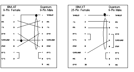
The NOM modules are equipped with a nine-pin RS-232C connector that supports Modicon’s proprietary Modbus communication protocol. The following is the Modbus port pinout connections for 9-pin and 25-pin connections.
The following figures show the Modbus port pinout connections for 9-pin (left) and 25-pin (right).
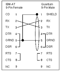
Modbus Ports Pinout Connections for Portable Computers
The following figure shows the Modbus port pinout connections for 9-pin portable computers.