|
Indicators
|
|
|
Original instructions
|

|
LED
|
Color
|
Description
|
|---|---|---|
|
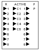
R
|
green
|
Module is READY (firmware initialization has been completed).
|
|
P
|
green
|
POWER - the US24 working voltage is present.
|
|
F
|
red
|
The red F-LED (F = fault) lights on the following faults:
|
|
ACTIVE
|
green
|
The PLC communication becomes active.
|
|
1 to 8
|
green
|
Displays the signal states of the discrete inputs IN1...IN8.
|
|
1 to 8
|
green
|
Displays the signal states of the discrete outputs OUT1...OUT8.
|
|
C1 to C5
|
green
|
Lights with the clock frequency applied to clock-inputs 5C1 to 5C5 respectively 24C1 to 24C5.
|