|
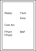
LED Indicators and Diagnostic Relay Behavior
|
|
|
Original instructions
|

|
LED
|
Color
|
State
|
Indication
|
|---|---|---|---|
|
Ready
|
Green
|
OFF
|
The module is unpowered or the internal logic is out of order.
|
|
ON
|
The module is powered and the internal logic is available.
|
||
|
ComAct
|
Green
|
OFF
|
No activity on the coaxial cable.
|
|
ON
|
Activity is detected on the coaxial cable.
|
||
|
FPort1
|
Green
|
OFF
|
No activity on the optical fiber port 1 reception.
|
|
ON
|
Activity is detected on the fiber port 1 reception.
|
||
|
FPort2
|
Green
|
OFF
|
No activity on the optical fiber port 2 reception.
|
|
ON
|
Activity is detected on the fiber port 2 reception.
|
||
|
Fault
|
Red
|
OFF
|
No error (internal or external) detected.
|
|
ON
|
An error (internal or external) has been detected.
|
||
|
Error
|
Red
|
OFF
|
No internal error detected.
|
|
ON
|
An internal error has been detected.
|
||
|
BrkF
|
Red
|
OFF
|
Activity is detected on both optical port inputs OR no activity has ever been detected on any optical port input.
|
|
ON
|
One of the optical fiber port input is inactive (see FPort• LED OFF) while activity is detected or has been detected on the other optical port input (see FPort• LED ON).
|