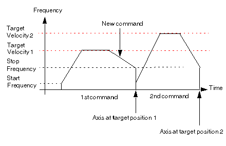
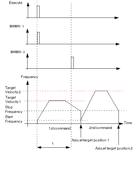
For the BlendingPrevious buffer mode, there can be two different cases:
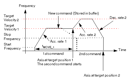
The new command is received by the PTO module during the acceleration phase or constant velocity phase of the previous command. As soon as the first target position is reached, the execution of the second command starts at the Target_Velocity of the previous command:
If there was no second command, the frequency profile would have followed the thick dotted line.
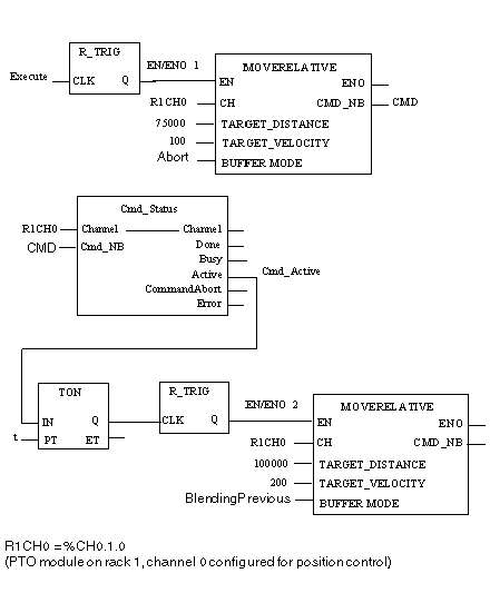
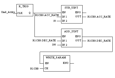
Program to obtain the above profile
NOTE: Program conditions for short movements:
When sending commands for short movements, please respect the following conditions:
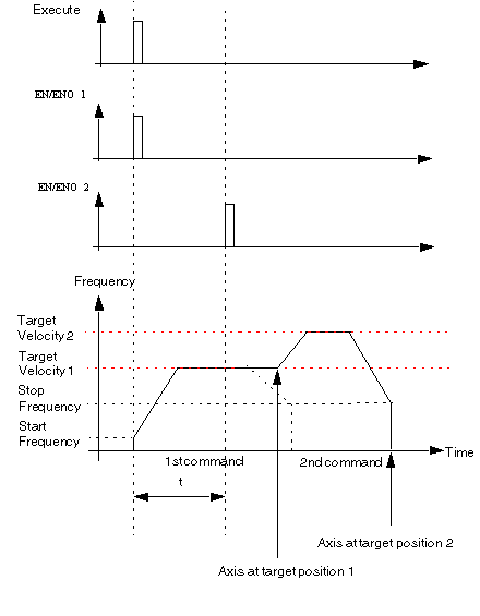
Where t is the time between two MOVE commands are sent to the PTO function. In the example program, t is the Preset delay time of the TON instance.
Time diagram of the MOVERELATIVE Input / Output
If the new command is received by the PTO channel during the stopping phase of the previous command, the sequence of the two commands is executed as "Buffered".
Time diagram of the MOVERELATIVE Input / Output
