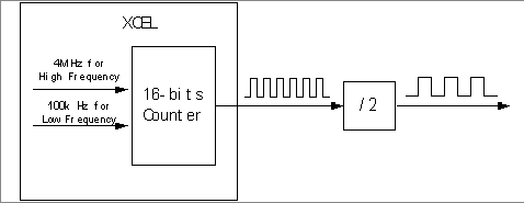
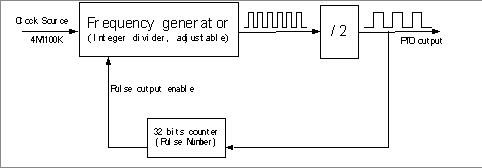
This function unit generates a Pulse Output as follows:
The internal counter uses 4 MHz as the Clock Source for high-frequency output from 100 Hz to 400 kHz.
The internal counter uses 100 kHz as the Clock Source for low-frequency output from 2 Hz to 100 Hz. (The output here refers to the one before external frequency-dividing circuit)
In high-frequency case, the output obtained directly from the internal counter has the frequency as 4M / Modulo (Modulo is an integral value, which is put into the counter to divide the Clock Source). We can see that a 4 MHz Clock Source is not sufficient to generate all the frequencies in the range from 100 Hz to 400 kHz with a 0.5% accuracy. For some frequencies, a specific algorithm is used to correct the output. This algorithm makes the output pulse vary between the Clock Source divided by Modulo and divided by Modulo+1. Aan appropriate variation ratio is implemented to make sure that the average frequency reaches a 0.5% accuracy.
For example, if the desired output frequency is 393 kHz:
The Modulo in this case is 10, the real output pulse will vary between 400 kHz and 363.6363 kHz, and the ratio is between 4:1 and 5:1.
The real output picture is as follows:
Pulse Generator Loop (2 ms):
There is a 32-bit counter in every PTO channel to count the pulse output number in order to ensure that there is no error on the pulse number.
Only one command can be sent and processed at each PLC task cycle.
In case of a sequence of commands:
-
If BufferMode is Aborted, the response time will be related to the PLC task cycle. That is to say that the current command will not be stopped, and the new command will not be started before the next cycle.
-
If BufferMode is Buffered or BlendingPrevious, the response time is independent from the PLC task cycle (considering that the command was sent at least one cycle before the current command is completed).


