|
|
Original instructions
|


|
Module status
|
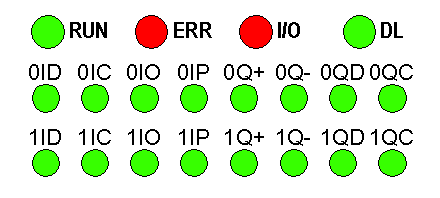
Status LEDs
|
|||
|---|---|---|---|---|
|
RUN
|
ERR
|
I/O
|
LEDs 0ID to 1QC
|
|
|
The unit is not receiving power or LEDs are out of order.
|
 |
 |
 |
x
|
|
The unit is configuring its channels
|
 |
 |
 |
x
|
|
Internal error detected in module
|
 |
 |
 |
x
|
|
No PTO Channel configured
|
 |
 |
 |
x
|
|
Unit in self-tests
|
 |
 |
 |
x
|
|
Unit has lost communication with CPU
|
 |
 |
 |
x
|
|
Channels are operational.
|
 |
 |
 |
LEDs 0ID to 1QC are representative of the state of the corresponding input/output:
 if Channel state active
 if Channel state inactive
|
|
I/O Error detected
|
 |
 |
 |
 Power lost
 Short-circuit / Overload (only for Output LEDs)
|
LED off LED Blinking (slow) LED flashing rapidly LED on |
||||
|
RUN
|
ERR
|
IO
|
DL
|
Status
|
|---|---|---|---|---|
 |
 |
 |
 |
Start of download
|
 |
 |
 |
 |
Download in progress
|
 |
 |
 |
 |
Download error
|
 |
 |
 |
 |
End of download
|
 |
 |
 |
 |
Upgrade done. Module to be restarted
|
 |
 |
 |
 |
Upgrade done with identical version. Module to be restarted
|
LED off LED Blinking (slow) LED flashing rapidly LED on |
||||